CHAPTER 3: INSTALLATION DIRECT INPUT AND OUTPUT COMMUNICATIONS
M60 MOTOR PROTECTION SYSTEM – INSTRUCTION MANUAL 3-35
3
Figure 3-33: Direct input and output dual-channel connection
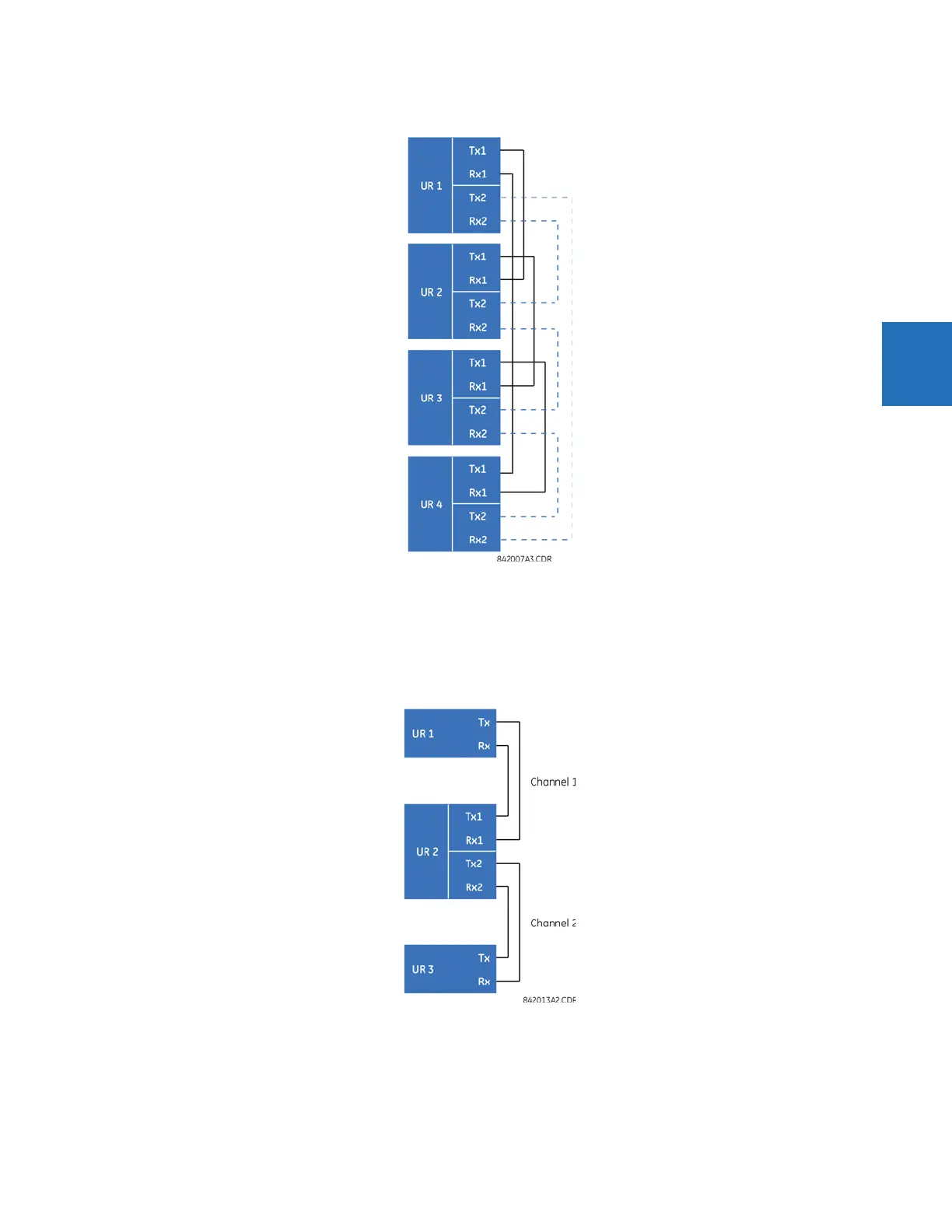
The following diagram shows the connection for three UR-series relays using two independent communication channels.
UR1 and UR3 have single type 7 communication modules; UR2 has a dual-channel module. The two communication
channels can be of different types, depending on the type 7 modules used. To allow the direct input and output data to
cross-over from channel 1 to channel 2 on UR2, set the
DIRECT I/O CHANNEL CROSSOVER setting to “Enabled” on UR2. This
forces UR2 to forward messages received on Rx1 out Tx2, and messages received on Rx2 out Tx1.
Figure 3-34: Direct input and output single/dual channel combination connection
The inter-relay communications modules are available with several interfaces and some are outlined here in more detail.
Those that apply depend on options purchased. The options are outlined in the Inter-Relay Communications section of the
Order Code tables in Chapter 2. All of the fiber modules use ST type connectors.