6. Control Functions and Parameter Settings
6-25
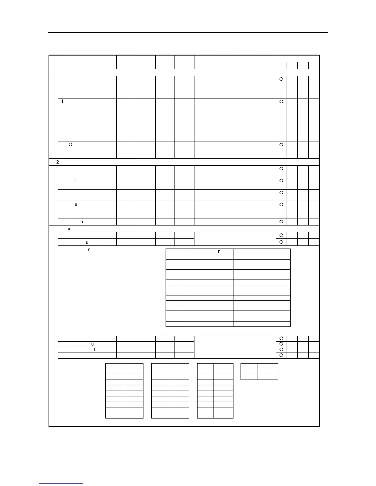
Block-C parameters (Basic function constants) list
ApplicationNo. Parameter Unit Default Min. Max. Function
ST V/f VEC PM
C11 – Operation panel mode setting
0 Initial mode 1. 1. 2. The initial operation mode for when
the power is turned ON is set
= 1 : Local
= 2 : Remote
1 Run command status 1. 1. 3. This is the initial operation mode at
power ON, during local operation
mode (operation from operation
panel) if the automatic start function
(C08-0 =2 or 3) is enabled.
.
= 1 : Stop = 2 : Forward run
= 3 : Reverse run
3 Operation panel
monitor settings
0.0 0.0 99.9 Set the monitor parameter No. to be
displayed initially when the power is
turned ON.
C12 – Setting input terminal function
0 FSV terminal input
mode
1. 1. 3. 1: 0 ~ 10V, 2: 0 ~ 5V, 3: 1 ~ 5V
1 FSI terminal input
mode
1. 1. 2. 1: 4 ~ 20mA, 2: 0 ~ 20mA
2 AUX terminal input
mode
1. 1. 3. 1: 0 ~ ±10V, 2: 0 ~ ±5V, 3: 1 ~ 5V
3 Filter time constant for
FSV/FSI and AUX
input
1. 1. 2. 1: 8ms 2: 32ms
4 AUX input gain 1.000 0.000 5.000
C13 – Output terminal function
0 FM output settings 0. 0. 9.
1 AM output settings 3. 0. 9.
Select the setting value from the
following table, and output.
The terminal voltage can be changed
freely with parameters C14-0.1
2 RC-RA output settings 0. 0. 24.
3 PSO1 output settings 3. 0. 24.
4 PSO2 output settings 7. 0. 24.
5 PSO3 output settings 8. 0. 24.
Select the setting value from the
following table, and output.
Value Parameter Output Voltage
0 Output frequency 10V at max. frequency
1 Setting frequency
Setting Speed
10V at max. frequency
10V at max. speed
2 Ramp output 10V at max. frequency
10V at max. speed
3 Output current (motor) 5V at motor rated current
4 Output current (drive) 5V at drive rated current
5 Output Voltage 10V at rated Voltage
6 Output power (drive) 5V at motor rated power
7 DC Voltage 5V at 300V (200V Series)
5V at 600V (400V Series)
8 OLT Monitor 10V at 100%
9 Heatsink Temperature 10V at 100ºC
10 Motor speed 10V at max. speed
Value Output
signal
Value Out