Components and Functions (Theory)
5-4 System view Versana Balance – Basic Service Manual
5808768-100 English Rev.9
5-2-2 Block Diagram
5-2-2-1 System Diagram
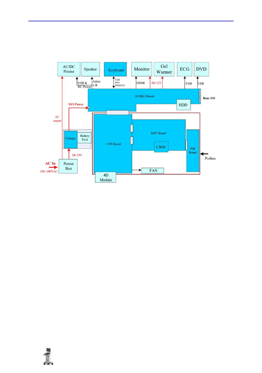
Figure 5-1. Versana Balance System Block Diagram
5-2-2-2 System Diagram Introduction
The system is composed with top modules, internal cage and
power box which is located at the bottom side of the machine.
The top modules include Keyboard, Speaker, Monitor (17.3 or
21.5 inch) and optional peripherals (AC/DC printer, ECG, DVD
and Gel warmer).
The internal cage has 4 PWAs: CWI, MST, PIB and CWD(
optional). System FANs are assembled in the Box.
IODKG board is fixed on the mechanical frame, this is the power
and I/O signals connection of internal cage.
4D module is mounted on internal cage.
The power box includes power switch and ACDC module which
provides DC19V power to system.

 Loading...


