GE HEALTHCAREDRAFT VOLUSON® P8 / VOLUSON® P6
DIRECTION 5459672-100, R
EVISION 6 DRAFT (JANUARY 17, 2013) PROPRIETARY SERVICE MANUAL
Chapter 3 - Setup Instructions 3-61
3-8-4 External I/O Connectors
3-8-4-1 External I/O Pin Outs
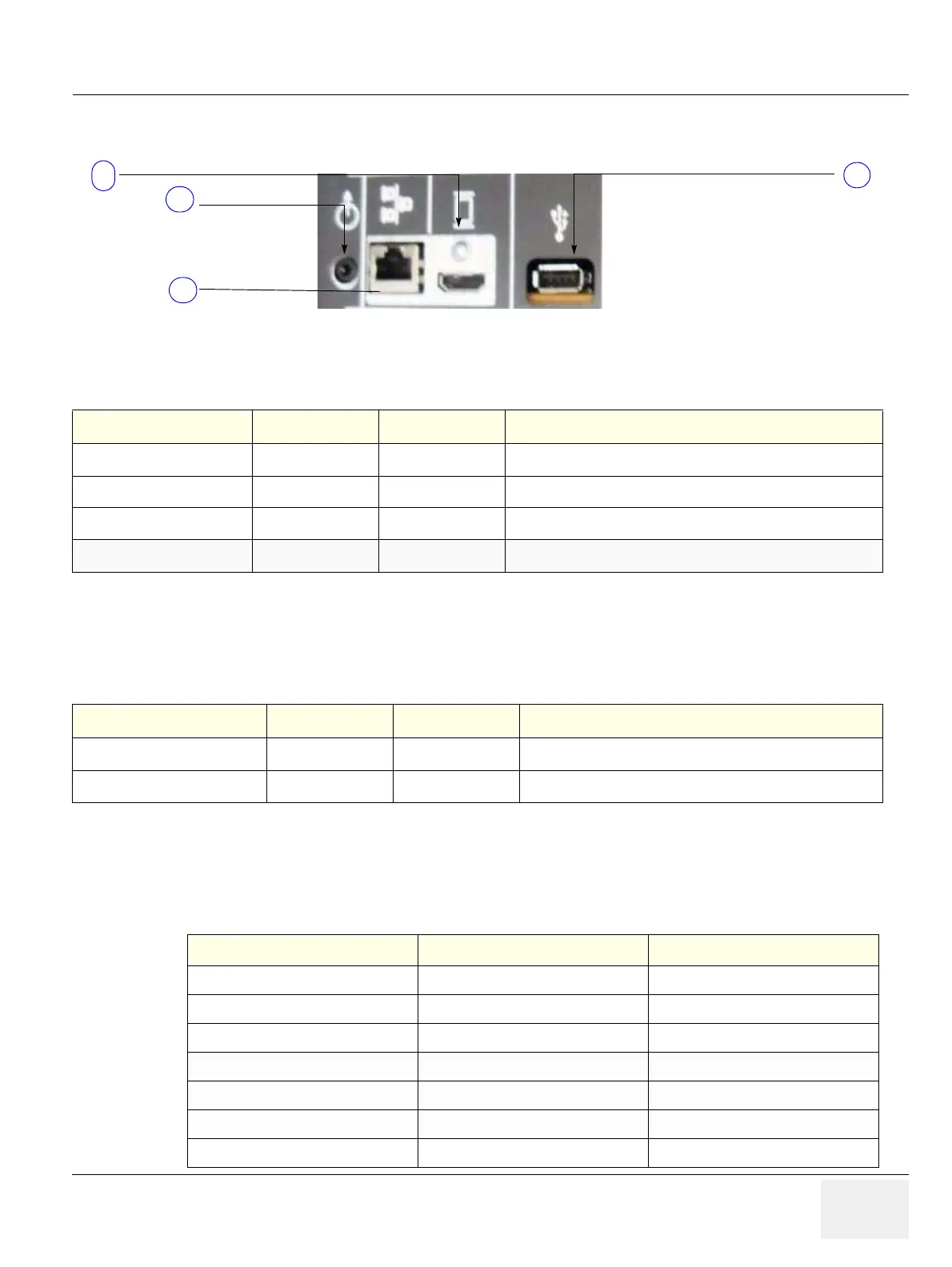
Figure 3-59 External I/O Connectors - on Rear of System
Table 3-9 External I/O Connector - Description
Connector Name Item Table Number Description
DVI Out
Table 3-11 Connector for external Monitor
NETWORK
Table 3-12 DICOM input/output, twisted pair RJ-45 10/100 megabit/s
USB
Table 3-13 USB-2.0 port
AUDIO
Table 3-13 Connector for External Speaker
Figure 3-60 External I/O Connectors - on TOP OPIO
Table 3-10 External I/O Connector - Description
Connector Name Item Table Number Description
USB
Table 3-13 USB-2.0 port
USB
Table 3-13 USB-2.0 port
Table 3-11 DVI out Connector, 19 Pin
Pin No Output Signal Description
1 ~ 12 TMDS clock/data TMDS clock/data
13 CEC CEC
14 N/C Reserved
14, 15 SCL/SDA I2C Line
17 DDC/CEC/HEC DDC/CEC/HEC
18 5V Power
19 Hot plug Hot plug
1
4
2
3
1
2
3
4
1
2

 Loading...


