ADP200 Application PID-IMM User Manual Pag. 6 of 80
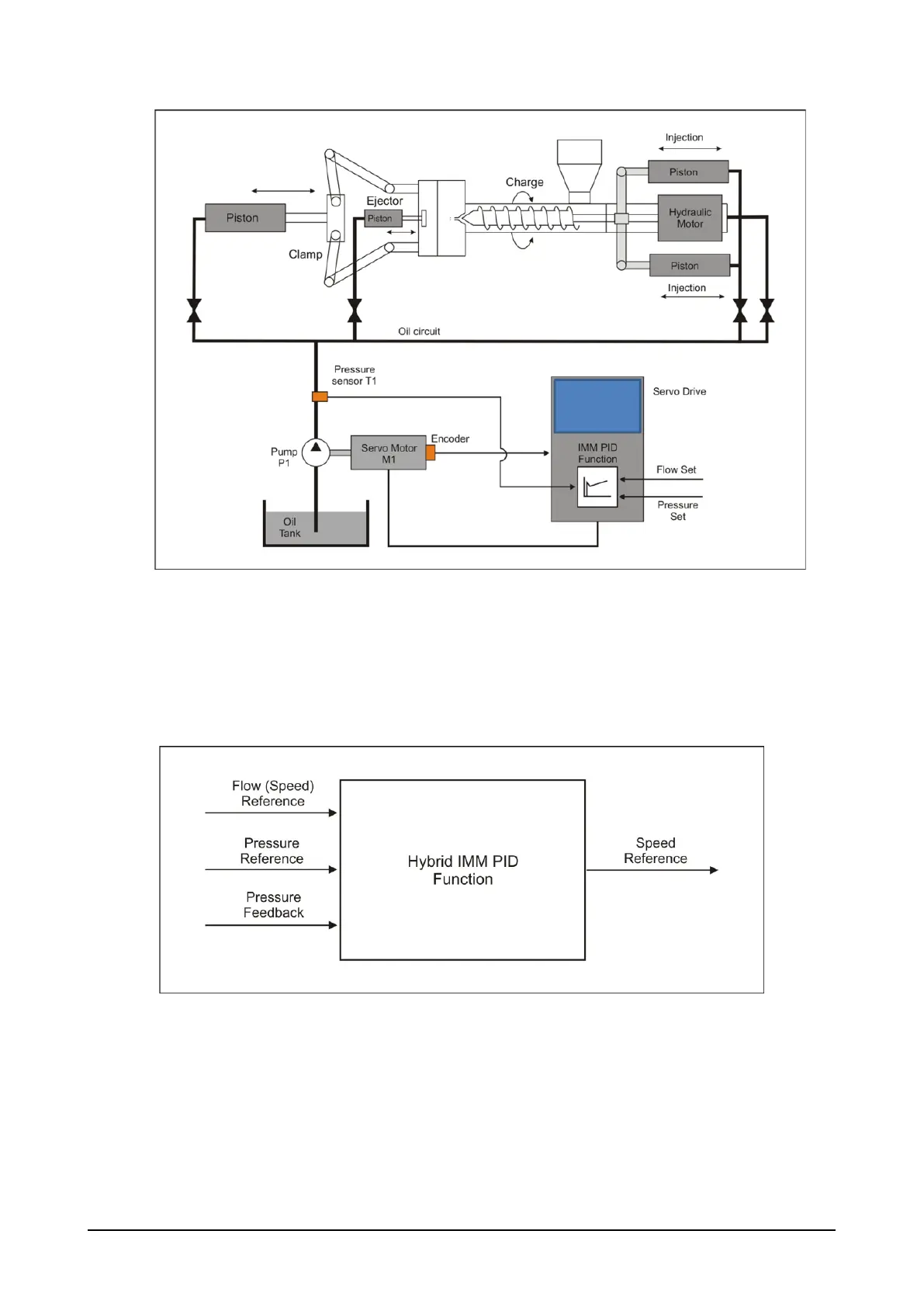
Figure 2 Servo Pump Controller
Machine PLC controls all movements and generates flow rate and pressure commanded profiles, usually
referred to each axis’ position (except for charge – screw), to be sent to drive through analog signals. Also in
conventional systems these references are sent via analog signals to the proportional valves.
The Hybrid IMM PID function can receive flow rate and pressure commands also via fieldbus interface.
On hybrid machines, due to gear pump operating principle, pump speed and consequently generated flow are
in direct proportion.
Figure 3: Hybrid IMM PID block diagram
The diagram below shows a typical pattern of the flow (speed) and pressure references during a complete
machine cycle.
Machine movements are sequentially managed and each axis is selected through directional valves that
open/close the respective hydraulic circuit.