ADV200 WA • Quick start up guide - Specification and installation 137
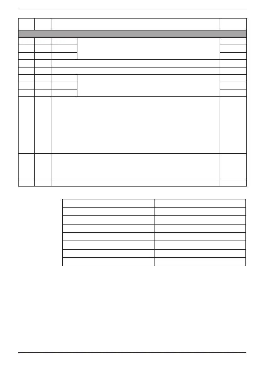
LEDS Colour FUNCTION
Normal
functioning
ALARM
H7 Red PHASE U
They light up to indicate a short circuit between the output phases
Off
H8 Red PHASE V Off
H9 Red PHASE W Off
H10 Red It lights up to indicate a power rectifier heat sink overtemperature Off
H11 Red It lights up to indicate overtemperature of the air inside the drive Off
H12 Red IGBT U
They light up to indicate loss of the feedback signal relating to the mo-
ment the IGBT devices are switched on. The signal is used for hardware
dead time compensation
Off
H13 Red IGBT V Off
H14 Red IGBT W Off
H15 Red
It lights up in case of overtemperature of one of the IGBT devices.
The signal temperature relating to the hotter of the master and slave IGBT devices is
sent to the regulation card.
A temperature signal is also sent automatically to the regulation card in case of mini-
mum temperature, which could occur in the event of a fault in one of the temperature
reading circuits.
The loss of one of the temperature signals is indicated by LED H15, with the code
indicated by the number of flashes (*): the sequence of flashes to indicate the faulty
PHASE or SLAVE has a 3Hz frequency and is repeated cyclically every 5 seconds.
Off
H18 Red
It lights up on the INT-P-ADV MASTER card to indicate that the drive’s total current
(master + slave) has exceeded the overcurrent value for the size of drive, whereas
it lights up on the INT-P-ADV SLAVE card to indicate that the SLAVE current has only
exceeded the overcurrent value of the SLAVE.
Off
H19 Red It lights up to indicate a fault on the DC-BUS power supply regulation card Off
(*) Led H15 code indicated by number of flashes NO. FLASHES
PHASE U 1
PHASE V 2
PHASE W 3
SLAVE 1 4
SLAVE 2 5
SLAVE 3 6
SLAVE 4 7

 Loading...


