ADV200 WA • Quick start up guide - Specification and installation 55
5.5 Typical connection diagrams
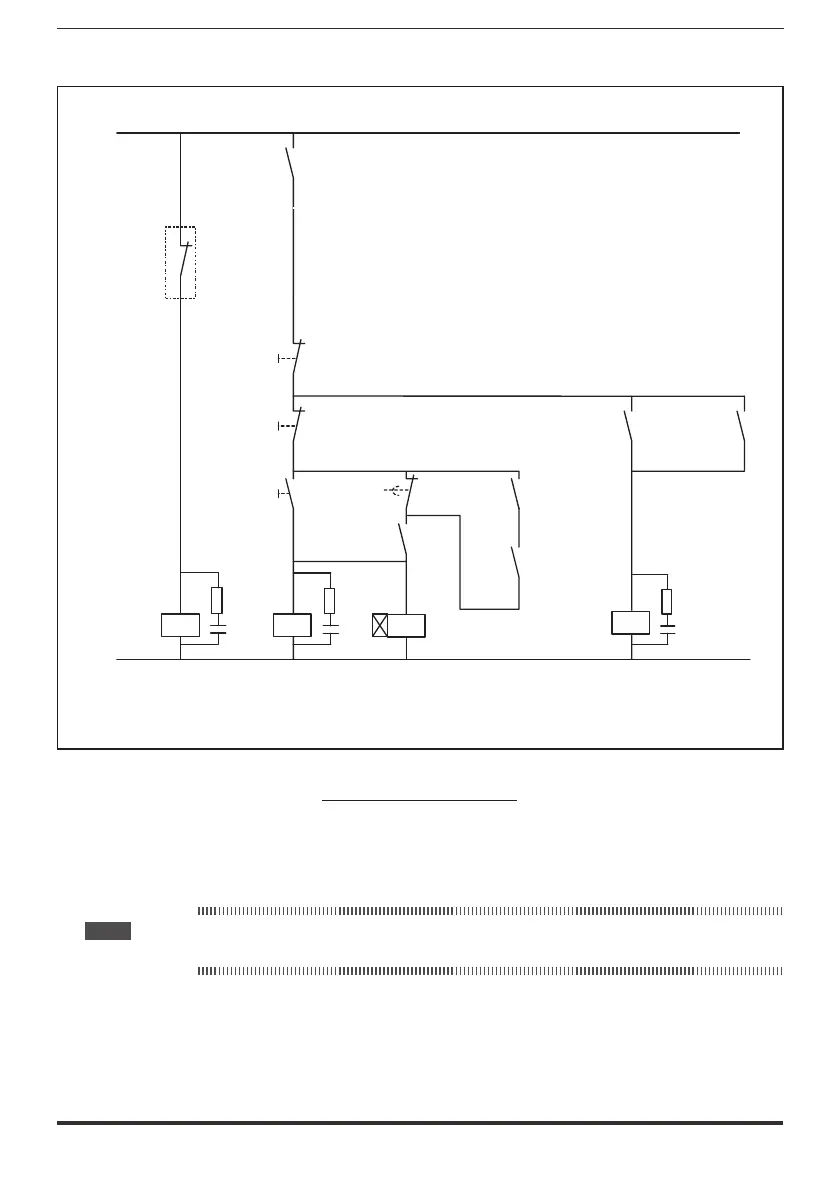
EMERGENCY-OFF
EMERGENCY-OFF
K0
K0
S11
Off
S12
Stop
S2
ON / Start
ON / OFF
Start / Stop
K2
K2T
K2T
K2
G1
R11
R14
Drive ok
t = 1 s
K2
K1M
K1M
Mains contactor
L01
L00
70
72
PRC ok (*)
(*): Only for sizes ≥ ADV200 WA-72000.
Figure 5.5.1: Auxiliary control circuits
Note: See ADV200 WA FP manual, chapter 26.14- PROCESS/MULTI PUMP for dedicated connection
diagram and sw configuration of multi-pump systems.
 Loading...


