48 ADV200 WA • Quick start up guide - Specification and installation
5.2.5 Power supply unit regulation card (only for sizes ≥ 72000)
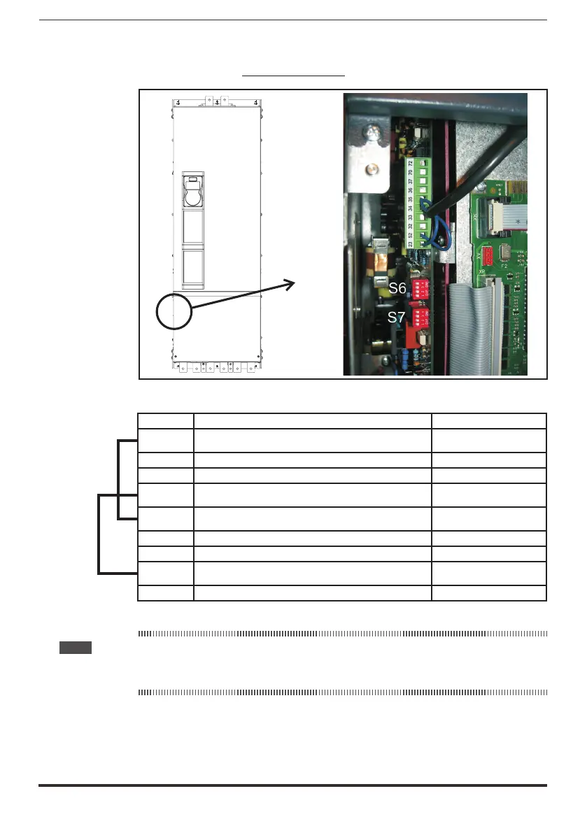
Figure 1: Terminals location
Terminals Function Voltage / Current
23 Input of the precharge enable control (15 - 35V, 5 - 11mA)
32 Output of the MLP static signal (low - active signal) (5 … 35V, 20mA source)
33 (Common) Ground of the MLP and ML static signals -
34 Reference point for Power supply +24V -
35 Power supply output +24V (32V / 300mA max)
36 Output of the ML signal (low - active signal) (5 … 35V, 20mA max sink)
37 Power supply of the ML and MLP signals (35V max)
52 (Common) Ground of the precharge enable control -
70, 72 OK Relay (max 250VAC, 1A – AC11)
Note! The jumpers shown are factory-wired.
Wiring of the OK relay contact (70 - 72) in series with the Enable chain of the ADV200 WA regulation
card is recommended.
Dip-switch and Jumper
S6 - S7 Selection of the AC mains frequency: 50 or 60 Hz

 Loading...


