44 ADV200 WA • Quick start up guide - Specification and installation
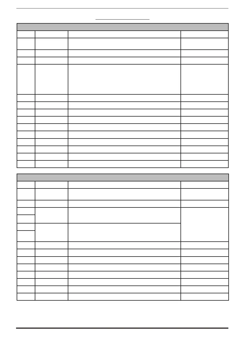
Table 5.2.3.1: Regulation terminals
Strip T2 (top)
Terminal Designation Function Max
R21
COM Digital
output 2
Common reference for digital output 2 (Relay 2) -
R24 Digital output 2 Programmable digital relay output 2 (NO). Default = Drive ready 250 Vac - 30 Vdc / 2A
5 Analog output 1 Analog output 1. Default = Null (not assigned) ±12,5 V (typical ±10 V / 5 mA)
6 Analog output 2 Analog output 2. Default = Null (not assigned)
- voltage (default):
±12,5 V (typical ±10V/5mA)
- current (set by S3 switch):
0...20mA or 4...20mA (setting by
PAR 1848, 15 - ANALOG OUPUTS
menu)
C1 COM Analog output Common reference for analog outputs and ±10V potential voltage reference -
7 Digital input E Digital input E . Default = Digital input E mon (Enable) 5mA @ +24V (+30V max)
8 Digital input 1 Digital input 1 . Default = FR forward src, PAR 1042 5mA @ +24V (+30V max)
9 Digital input 2 Digital input 2 . Default = FR reverse src, PAR 1044 5mA @ +24V (+30V max)
10 Digital input 3 Digital input 3 . Default = Multi ref sel 0 src 5mA @ +24V (+30V max)
11 Digital input 4 Digital input 4 . Default = Multi ref sel 1 src 5mA @ +24V (+30V max)
12 Digital input 5 Digital input 5 . Default = Fault reset src 5mA @ +24V (+30V max)
C2 COM Digital inputs Common reference for digital inputs -
C3 0V 24 OUT Reference point for +24V OUT -
S3 + 24V OUT +24V supply for IO 150 mA (Resettable fuse), ±10 %
Strip T1 (bottom)
Terminal Designation Function Max
R11
COM Digital
output 1
Common reference for digital output 1 (Relay 1) -
R14 Digital output 1 Programmable digital relay output 1 (NO). Default = Drive OK 250 Vac - 30 Vdc / 2A
1
Analog input 1
Programmable / configurable analog differential input.
Signal: terminal 1. Reference: terminal 2.
Default = Multi ref 0 src
- voltage (default):
±12,5 V (typical ±10V/1mA)
- current (set by switches S1-S2):
0...20mA or 4...20mA (set by
PAR 1502 or 1552, 14 - ANALOG
INPUTS menu)
2
3
Analog input 2
Programmable / configurable analog differential input.
Signal: terminal 3. Reference: terminal 4.
Default = Not used
4
S1+ +10 V Voltage reference +10V; reference point: C1 terminal +10 V ±1% / 10 mA
S1- - 10V Analog output -10V; reference point: C1 terminal -10 V ±1% / 10 mA
13 Digital output 3 Digital output 3. Default = Speed is 0 delay +24 V / 20 mA (typ), 40 mA (max)
14 Digital output 4 Digital output 4. Default = Ref is 0 delay +24 V / 20 mA (typ), 40 mA (max)
IS1 PS Digital output Digital outputs 3 / 4 power supply -
IC1 COM Digital output Common reference for digital outputs 3 / 4 -
IC2 0V 24 EXT Reference for regulation card 24V external supply -
IS2 + 24V EXT External supply of regulation card +24V ±10% / 1A
 Loading...


