72 ADV200 WA • Quick start up guide - Specification and installation
Step 1 - Connections
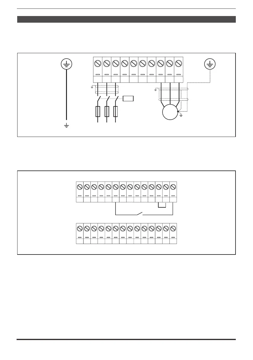
Connect the drive to the power supply as illustrated in the following diagrams:
Connection to the mains and motor
L1 L2 L3 BR1 BR2 C D U V W
K1M
L1 L2 L3
F1
(3ph - 400 V / 460 V 50/60 Hz)AC AC,
M
3 ph
For ADV-...-DC versions please refer to the diagrams in paragraph “5.1.6 Power line
connection”, page 33 and “5.1.8 Motor connection”, page 37.
Connection of the drive enabling contact
R21R24 5 6 C1 7 8 9 10 11 12 C2 C3 S3
R11R14 1 2 3
4
S1+S1- 13 14 IS1 IC1
IC2
IS2
Enable
Checks to be performed before powering the drive
• Check that the supply voltage is correct and that the input terminals on the
drive (L1, L2 and L3) are connected correctly.
• Check that the output terminals on the drive (U, V, and W L1, L2 and L3 or C
and D for ADV-...-DC) are connected to the motor correctly.
• Check that all the drive control circuit terminals are connected correctly. Check
that all control inputs are open.
Powering the drive
• After completing all the checks described above, power the drive and proceed
to Step 2.

 Loading...


