50 ADL300 • Quick installation guide - Specifications and connection
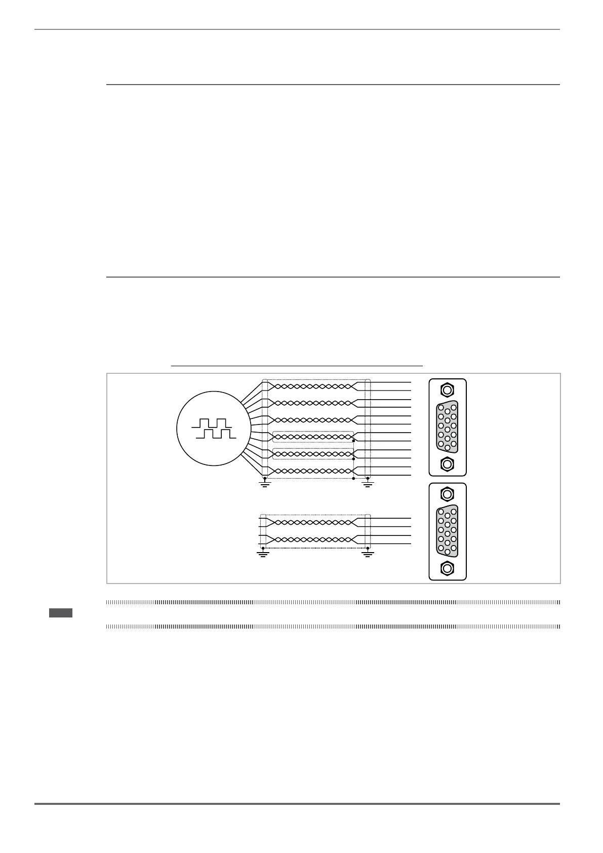
(7) Repeat Encoder (TTL line-driver)
ADL300B-...-E24R have an incremental encoder output with TTL Line Driver levels (according to the main encoder
supply) to be used to repeat the servomotor feedback device. This function is performed via HW and an encoder output
can be repeated with a programmable divider. The encoder output signals are available on the XER connector:
20
21
22
23
B- out
B+ out
A- out
A+ out
(*)
XER
(*) Connection of shielding, see gure 7.2.4
Technical specication:
Channels ������������������������������� A+ A-, B+ B-, differential line drivers, optoisolated.
Max frequency �������������������������� 200 kHz
Number of impulses ���������������������� 1/1-1/2-1/4-1/8 repeat (default 1/1)
Electrical interface ������������������������ TTL (ref. GND) Ulow ≤ 0.5V Uhigh ≥ 2.5V Typ 3.5V
Load capacity ��������������������������� TTL 20mA @ 5,5V (Zin 120Ω) for each channel
Cable length ���������������������������� max 50m
7.2.4 Integrated Safety Card Connection
EXP-I/O-... card EXP-DE-... card
EXP-SE-... card
EXP-EN-... card
EXP-HIP-... card
R-ADL300A card
RC-ADL300A card
CAN
(RC-ADL300A only)
PC
(RS232)
Keypad
(RS485/422)
XO
XE
XC
XS2
XS1
T3 T2 T1 XER
XE
SAFETY
The SAFETY EN+, SAFETY EN+, SAFETY OK1 and SAFETY OK2 terminals must be connected as shown in the typi-
cal connection diagrams in chapter 7.3.2.
Safety card management is now integrated in the rmware.
The Safety card must be enabled to enable the drive (menu 9 - COMMANDS, PAR 1010 Commands safe start,
Default = 1).
The drive is disabled if the Safety card enable command is removed while it is enabled.
To re-enable the drive, re-enable the Safety card then remove and re-send both the Enable and Start commands.

 Loading...


