ADL300 • Quick installation guide - Specifications and connection 49
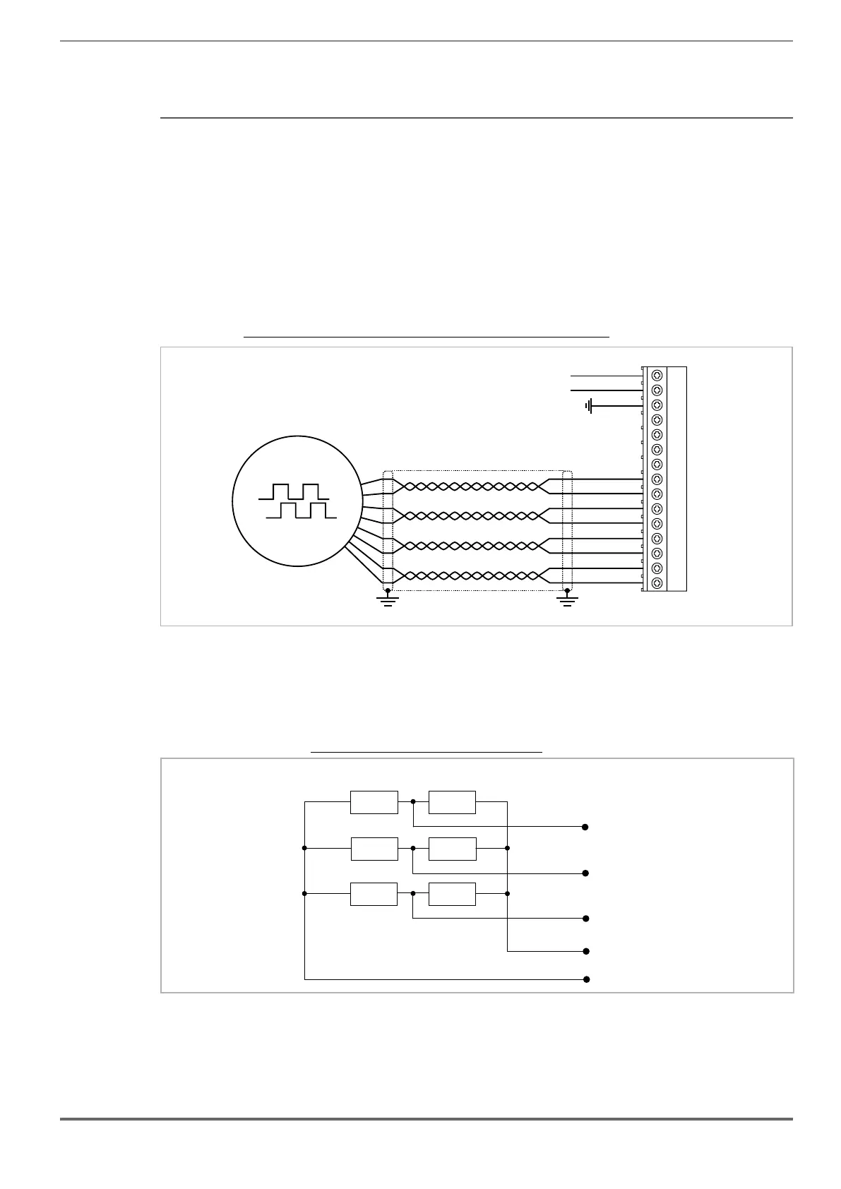
(6) Connection Sinusoidal SinCos Encoder + repetition (ADL300B-...-AD1) (SESC)
Technical specication (XE):
Channels ������������������������������� A+ A-, B+ B-, Z+ Z-, Sin+ Sin-, Cos+ Cos-, differential
Management of loss of encoder signals.
Max frequency �������������������������� 200 kHz (check the number of encoder impulses according to the maximum speed)
Number of impulses ���������������������� min 128, max 16384 (default 1024)
Electrical interface ������������������������ Channels A/B/Sin/Cos 0.6 V ≤ Vpp ≥ 1.2 V (typ. 1.0 V) − Channel Z* 0.2 V ≤ Vpp ≥ 0.8 V
Load capacity ��������������������������� Channels A/B/Z* 8 mA @ 1.0 Vpp (Zin 120Ω)
Channels Sin/Cos 1 mA @ 1.0 Vpp (Zin 1kΩ)
Programmable internal power supply ���������� min +5.2 V, max +6.1 V (default + 5.2 V) − Imax 150 mA.
The internal power supply of the encoder can be selected from the keypad (ENCODER CONFIG
menu, parameter Encoder supply (PAR 2102) to balance the loss of voltage due to the length of
the encoder cable and load current.
PAR 2102 Encoder supply range: min=5.2V, max= 6.1V, step of 0.1V; default=5,2V.
The encoder supply voltage will be rounded off to the nearest value among those 4 values avail-
able via hw: 5.2V / 5.5V / 5.8V / 6.1V.
Cable length ���������������������������� max 50m
* Channel Z = I (Index mark)
Technical specication (XER):
Channels ������������������������������� A+ A-, B+ B-, differential line drivers, optoisolated.
Max frequency �������������������������� 200 kHz
Number of impulses ���������������������� 1/1-1/2-1/4-1/8 repeat (default 1/1)
Electrical interface ������������������������ TTL (ref. GND) Ulow ≤ 0.5V Uhigh ≥ 2.5V Typ 3.5V
Load capacity ��������������������������� TTL 20mA @ 5,5V (Zin 120Ω) for each channel
Cable length ���������������������������� max 50m
Figure 7.2.10: Connection Sinusoidal SinCos Encoder + repetition (ADL300B-...-AD1) (SESC)
COS-
COS+
SIN-
SIN+
A-
A+
0VE out
+VE out
Z-
Z+
B-
B+
1
5
11
15
6
10
XE
13
12
11
10
4
3
1
8
6
5
7
9
B- out
B+ out
A- out
A+ out
1
5
11
15
6
10
XER
1
8
6
5
Note! See the figures above for wiring the sinusoidal and digital encoder. Remember that the cup connector has a different pinout numbering.

 Loading...


