To Adjust Chain Tension
1. Raise the loader off the ground following the
“Loader Raising Procedure” topic at the beginning
of this chapter.
2. Remove the access cover located between the
wheels to gain access to the drive chain front and
rear take-up assemblies.
3. Rotate the front and rear tires (by hand) towards
each other so the slack sides of the chains are at the
top.
4. Working through the access hole, loosen the lock
nut then the flanged lock nut on either of the two
chains.
5. Begin tightening the adjustment nut. This will cause
the idler assembly to lower, thereby increasing
tension on the chain.
6. The correct chain deflection is 1/2" (12 mm)
minimum on the side opposite from the adjuster -
halfway between the sprockets (fig. 7-2).
7. After the proper chain tension is obtained, retighten
the flanged lock nut and lock nut.
IMPORTANT: Over-tightening the drive chain will
cause premature drive chain and axle sprocket
wear.
8. Repeat steps 4 through 7 for the other chain.
9. Reinstall the chaincase access covers using oil
resistant RTV or equivalent between the cover and
the chaincase. If necessary, replenish the chaincase
oil level until oil runs out of the oil level check plug
(fig. 7-2).
10. Repeat steps 2 through 9 for the other side of loader.
11. Follow the “Loader Lowering Procedure” topic at
the beginning of this chapter to return the loader to
the ground.
PRINTED IN USA 49 907808/CP0300
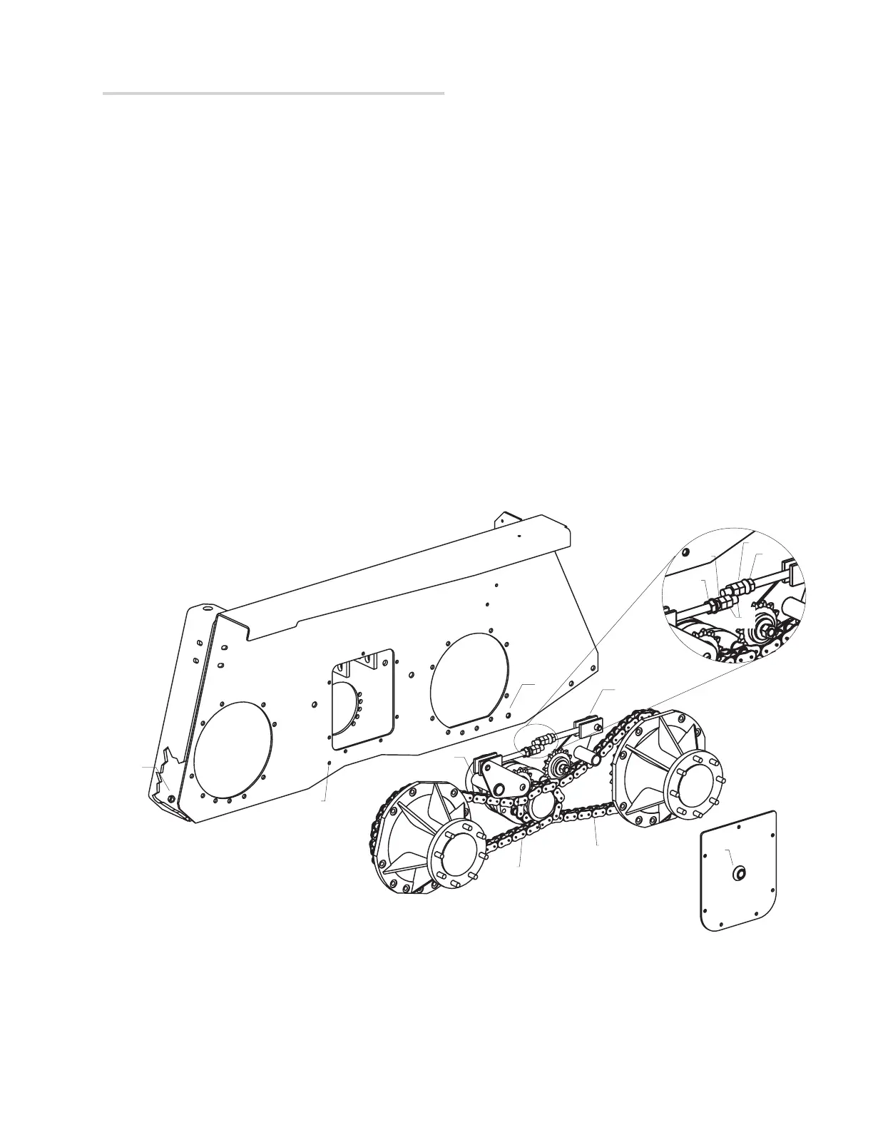
Fig. 7-2: Adjusting Drive Chain Tension - Left side shown, right side typical
1. Front Adjuster 6. Front Chain Drive
2. 3/4” Flanged Lock Nut 7. Rear Drive Chain
3. 3/4” Adjustment Nut 8. Drain Plugs
4. Lock Nut 9. Oil Level Check Plug
5. Rear Adjuster 10. Oil Fill Plug
8
9
8
7
6
10
5
2
3
2
3
4
1