Electric Auxiliary Controls
Adjustment (Fig. 7-3)
If your loader is hand & foot operated, it may be
equipped with electrically controlled auxiliary
hydraulics. Follow the procedure below for adjustment
of those controls.
1. With the panel switch down, adjust potentiometer
#2 clockwise until a squealing or ticking in the
actuator is heard or felt. Turn counterclockwise
slightly to obtain full retraction without squealing or
ticking. Continue turning counterclockwise another
1/8 of a turn.
2. With the panel switch down and the handle switch to
the left, adjust potentiometer #4 counterclockwise
until a squealing or ticking is heard or felt. Turn
clockwise slightly to obtain full extension without
squealing or ticking. Continue turning clockwise
another 1/8 of a turn.
3. With the panel switch up, adjust potentiometer #1
counterclockwise until a squealing or ticking is
heard or felt. Turn clockwise slightly to obtain full
extension without squealing or ticking. Continue
turning clockwise another 1/8 of a turn.
4. With the handle switch to the left, adjust
potentiometer #3 clockwise until a squealing or
ticking is heard or felt. Turn counterclockwise
slightly to obtain full retraction without squealing or
ticking. Continue turning counterclockwise another
1/8 of a turn.
907808/CP0300 50 PRINTED IN USA
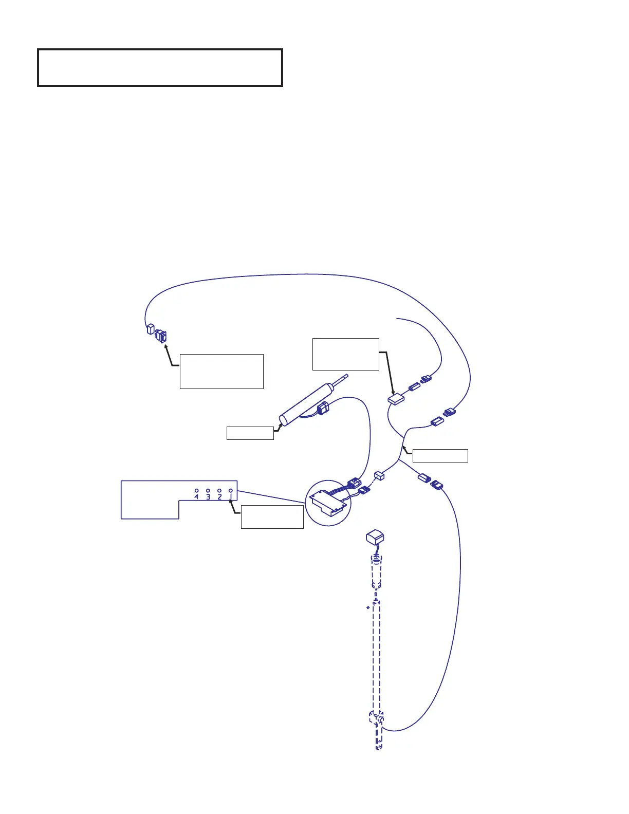
Fig. 7-3: Electric Auxiliary Controls Adjustment
Rocker switch
located on
instrument panel
Actuator
Fuseholder with
5 amp AGC
Blade-type fuse
Gehl harness
Potentiometer
numbers
Controller
From engine harness power -
left front of engine
Clockwise = Retract