4
1.2 Installation
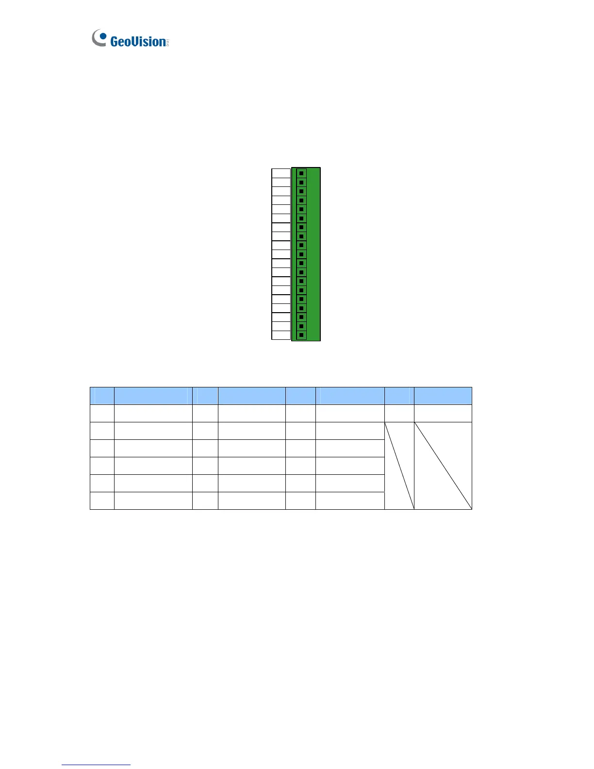
Please open GV-AS100 cabinet and wire the necessary connections to the terminal block as
illustrated below.
Door
19 NO
Door
18 NC
Door
17 COM
Alarm
16 NO
Alarm
15 COM
14 IN
COM
13 IN3
Fire
12 IN2
Button
11 IN1
Sensor
GND
10
PWR Out
9 12V
Data1
8
Data0
7
RS485
6 B-
RS485
5 B+
RS485
4 A-
RS485
3 A+
GND
2
PWR In
1 12V
Figure 1-3
Pin Function Pin Function Pin Function Pin Function
1 12V 7 Data 0 13 Fire IN3 19 Door NO
2 GND 8 Data 1 14 IN COM
3 RS-485 A+ 9 12V 15 Alarm COM
4 RS-485 A- 10 GND 16 Alarm NO
5 RS-485 B+ 11 Sensor IN1 17 Door COM
6 RS-485 B- 12 Sensor IN2 18 Door NC
 Loading...


