GV-AS400 Controller
107
3
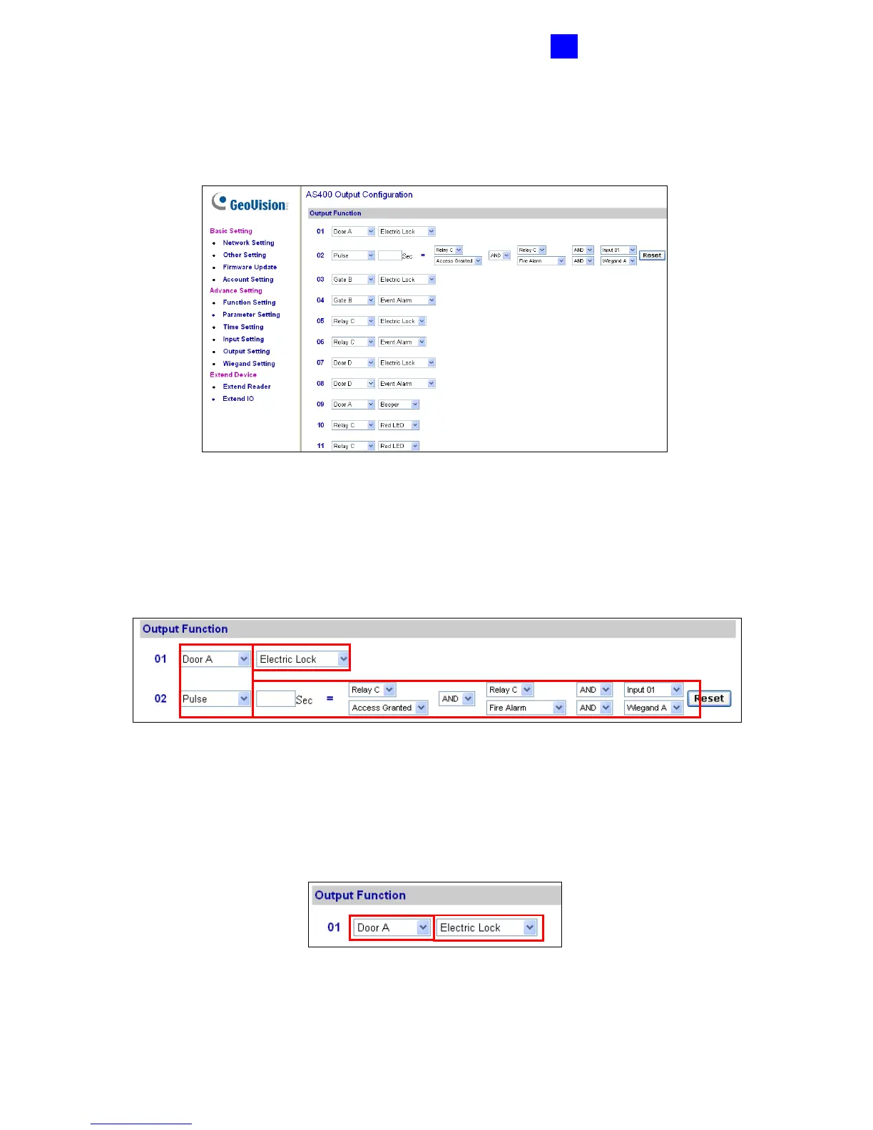
3.4.3.E Output Function
In the left menu, click Output Function. This AS400 Output Configuration page appears.
Figure 3-23
Here you can define each output device that is connected to GV-AS400, such as locking
devices and Exit Button. Select from the drop-down list to configure the Output Type (No. 1,
Figure 3-24). Depending on the chosen Output Type, either Output Function (No. 2,
Figure 3-24) or Output Conditions (No. 3, Figure 3-24) will become available.
Figure 3-24
Output Function Settings:
When Output Type (No. 1, Figure 3-25) is set to be Door #, Gate # or Relay #, the options
similar to the figure below become available.
Figure 3-25
1
2
3
1
2
 Loading...


