GV-AS400 Controller
87
3
To connect GeoFinger readers:
If more than one GeoFinger reader is connected to GV-AS400, an extra power supply is
required to drive each GeoFinger reader. Use 12V pins on the Weigand connectors to power
on each GeoFinger reader.
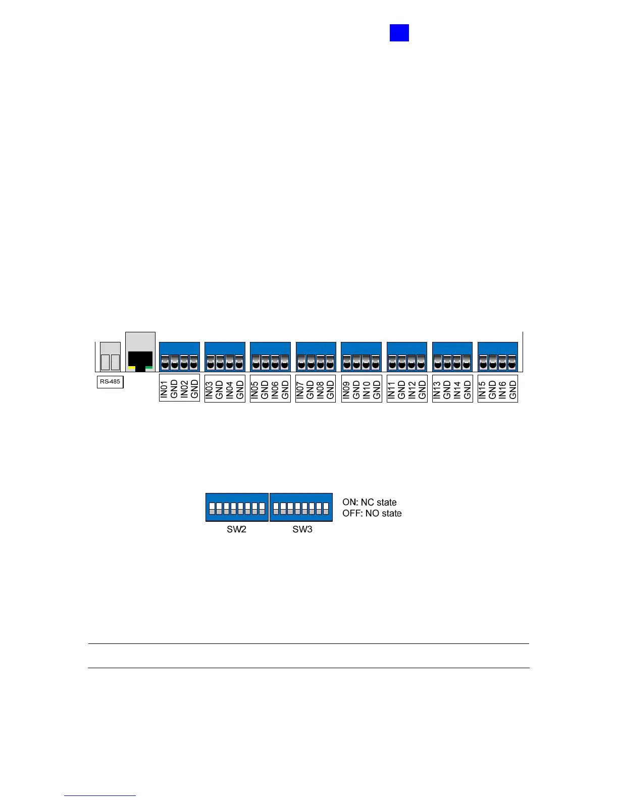
3.2.2 Connecting Input Devices
GV-AS400 provides up to 16 inputs. All inputs are dry contact that can be configured as
normally open (NO) or normally closed (NC).
Each input has an LED indicator that turns ON to provide a visual indication that the input
device is activated.
Figure 3-4
Use the switch, as shown below, to change the input state for NO or NC. When the switch is
pushed up, the state is NC. When the switch is pushed down, the state is NO. SW2 is used
for inputs 1 to 8 and SW3 is for inputs 9 to 16.
12345678
ON EGE
12345678
ON EGE
Figure 3-5
Besides having the on-board capability of monitoring 16 inputs, GV-AS400 can be expanded
to 64 inputs if 4 units of GV-IO Boxes (16 Ports) are connected. For details, see 3.2.6
Connecting External I/O Box.
Note: GV-AS400 does not support the input devices of wet contact.
 Loading...


