GV-AS400 Controller
85
3
3.2.1.A Wiegand Readers
GV-AS400 provides 8 Wiegand inputs (Wiegand A to Wiegand H) for connection of Wiegand
readers ranging from 26 to 64 bits. The table below shows the pin assignments of Wiegand
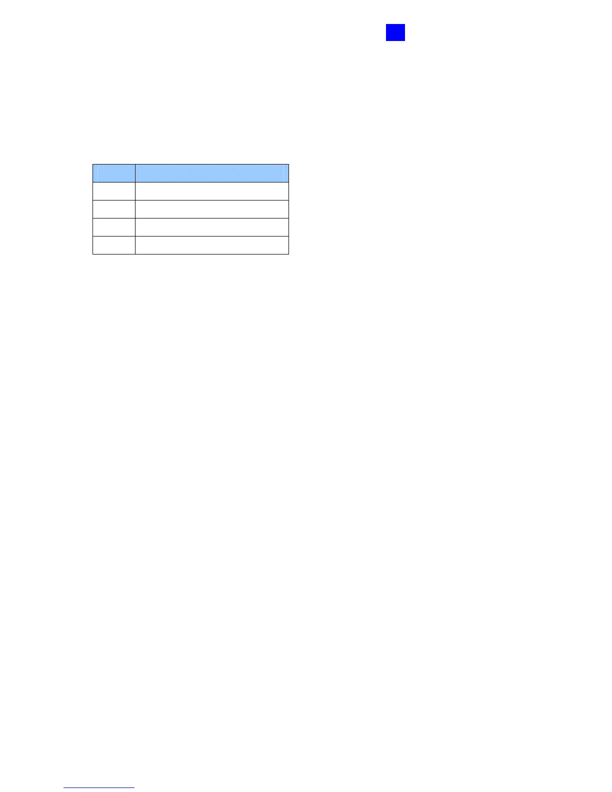
inputs on GV-AS400. Please consult the documentation of your Wiegand reader for wiring.
Pin Function
GND GND of the Power Supply
D0 Wiegand Data 0
D1 Wiegand Data 1
12V 12V Power Supply
If your Wiegand reader is equipped with LED or beeper that can be controlled externally, you
can connect the control wires to outputs 9 ~ 16 on GV-AS400. For the connection, see
3.2.3.B Outputs 9 ~ 16.
 Loading...


