38
CHAPTER 4
Tool Settings
F1
OPERATIONAL SETUP
Settings System
Misc.
ENTER for Main Menu
F3
CURRENT SETTINGS
Speed Force
Accel Corners
ENTER for Main Menu
F1
F4
F2
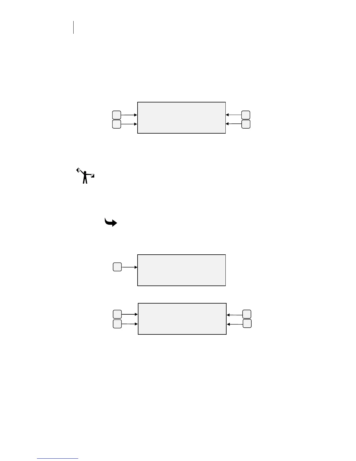
2
On the Settings menu, press F1 Default, to use the present tool settings
for the select material. Press F2, Corners, to change the setting.
(Scotchcal 220 is shown as an example. Corners change applies to the
material shown in the menu.)
3
Press the F1 or F2 key to decrease the corner sharpness, or press the F3
or F4 key to increase the corner sharpness. For each keypress, the bar
graph extends to the left or right one increment to indicate the amount
of change.
4
Press the ENTER key to accept the new setting, or press CANCEL to
discard it, and return to the Settings menu. This corners adjustment
applies only to the currently selected material.
Note: Changes can be made while a job is running. In this menu, pressing
CANCEL discards the changes. It does not cancel the job unless CANCEL is
pressed a second time or you are in Edit mode.
A change made to corners DURING a job might not take effect immediately.
Data currently in plotter memory must be plotted before your change takes
effect.
To make specific numeric changes at the plotter control panel
1
Press F3 while holding down the ENTER key for the Operational
Setup menu.
2
Press F1, Settings, to get the Current Settings menu.
3
Press F4, Corners, to see the current value for each setting.
SHARP CORNERS
- less 0 more +
..........
]]]]]
]]]]]]]]]]
]]]]]
ENTER Key to Accept
F3F1
F2 F4