- 26 -
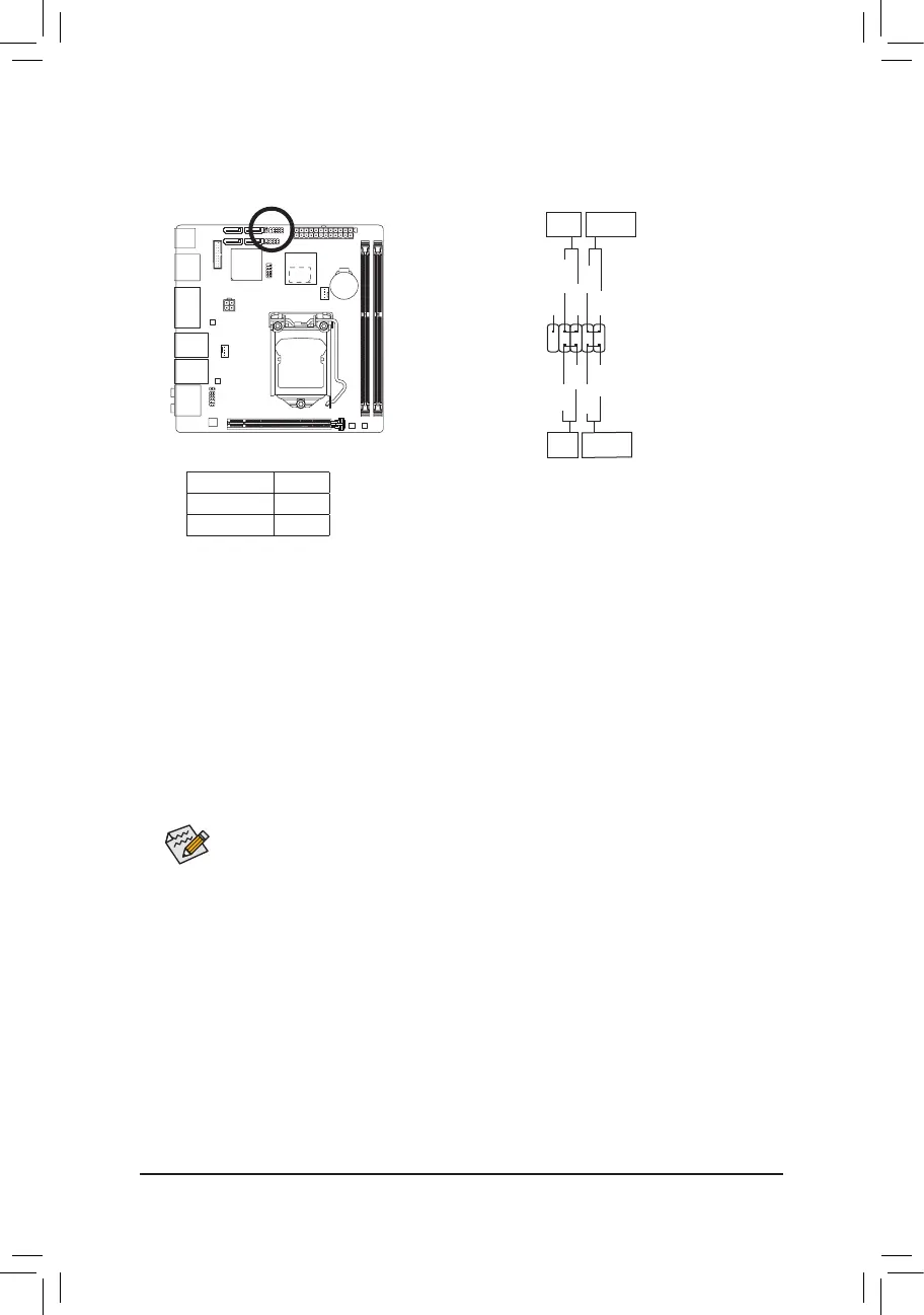
8) F_PANEL (Front Panel Header)
Connectthepowerswitch,resetswitch,andsystemstatusindicatoronthechassistothisheaderaccording
to the pin assignments below. Note the positive and negative pins before connecting the cables.
10
9
2
1
RES-
HD+
RES+
HD-
PW+
MSG+
PW-
MSG-
NC
Hard Drive
Activity LED
Reset
Switch
Message/
Sleep LED
Power
Switch
Thefrontpaneldesignmaydifferbychassis.Afrontpanelmodulemainlyconsistsofpowerswitch,
resetswitch,harddriveactivityLEDandetc.Whenconnectingyourchassisfrontpanelmodule
tothisheader,makesurethewireassignmentsandthepinassignmentsarematchedcorrectly.
• PW (PowerSwitch,Red):
Connectstothepowerswitchonthechassisfrontpanel.Youmaycongurethewaytoturnoffyour
systemusingthepower switch (refer toChapter2,"BIOS Setup," "Power Management,"formore
information).
• HD (HardDriveActivityLED,Blue):
Connects to the hard drive activity LED on the chassis front panel. The LED is on when the hard drive
is reading or writing data.
• RES (ResetSwitch,Green):
Connects to the reset switch on the chassis front panel. Press the reset switch to restart the computer
ifthecomputerfreezesandfailstoperformanormalrestart.
• NC(Purple):
No connection.
• MSG (Message/SleepLED,Yellow):
Connects to the power status indicator on the chassis front panel. The LED
is on when the system is operating. The LED is off when the system is in S3/
S4sleepstateorpoweredoff(S5).
System Status LED
S0 On
S3/S4/S5 Off
 Loading...