SOUL S5110/ART 7W VIDEO DOOR ENTRY SYSTEM KIT
10
Installation
ART 7W/G2+ MONITOR
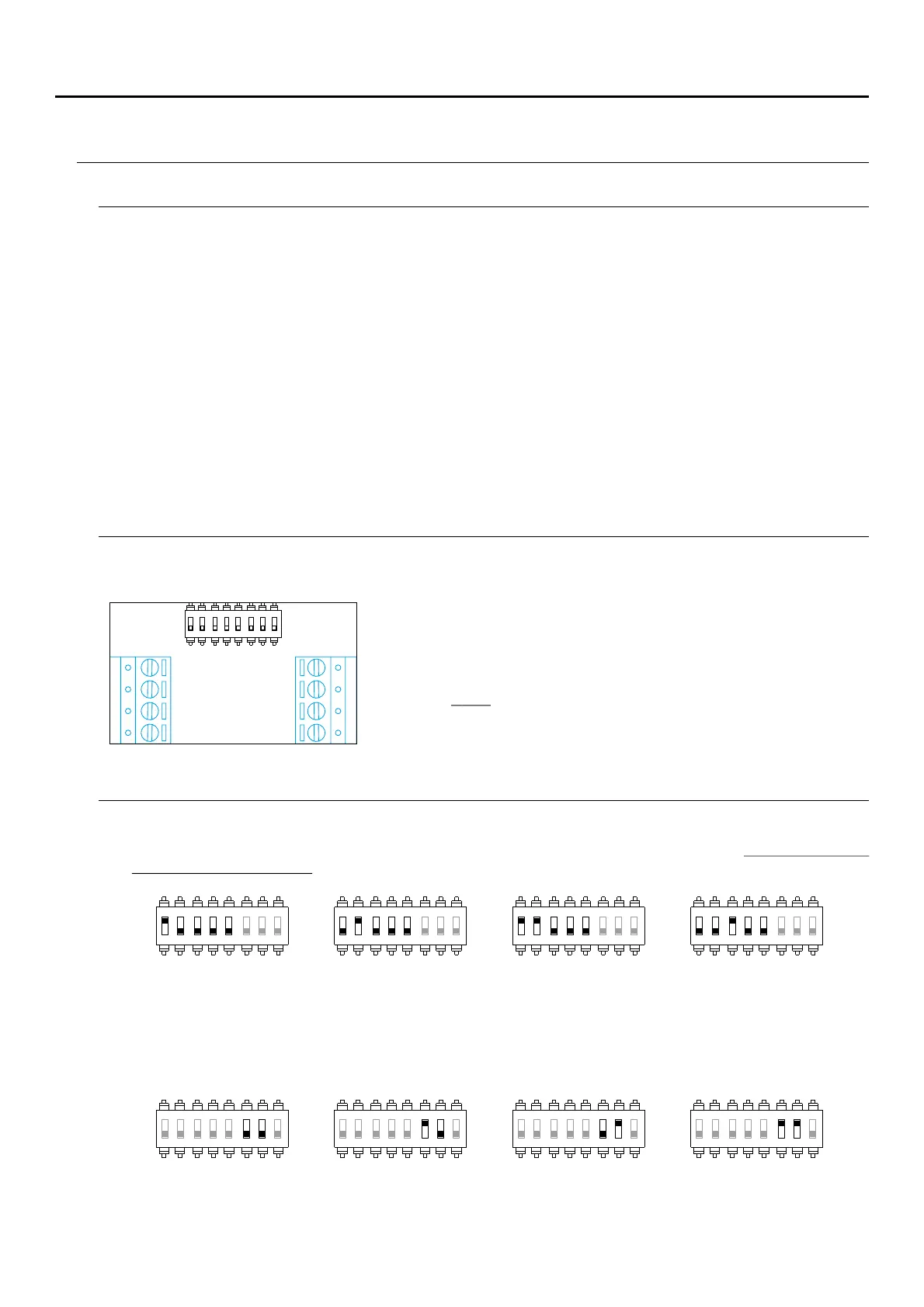
Installation terminals (K)
For ease of installation, the installation terminals are removable and supplied in a separate bag. Once the
terminals are wired, place them in position.
24V, : local power input.GND
BUS BUS, : communications bus (non-polarised).
SA GND, : auxiliary call repeater output (maximum 50mA/12V).
HZ HZ, : apartment front door button input:
Note: ART 7W/G2+ monitor 'V.01 + No. 6539 and V.02' or
later: Connect only on the master monitor. The signal received
is then transmitted to the slave monitors in the same apartment
through the BUS.
SA
GND
HZ
HZ
BUS
BUS
24V
GND
ON
1 2 3 4 5 6 7
8
Configuration switches (R)
Switches 6 and 7.
These define whether the monitor is master or slave. Each apartment must have one master monitor, and only
one. In the case of apartments with more than one monitor, the monitor with Wi-Fi transmitter should always be
the master.
This activates the end-of-line resistance in the ON position. Activate it in monitors where the bus cable ends.
Deactivate it only in intermediate monitors.
Switch 8.
Slave 1 Slave 2 Slave 3Master
ON
1 2 3 4 5 6 7 8
ON
1 2 3 4 5 6 7 8
ON
1 2 3 4 5 6 7 8
ON
1 2 3 4 5 6 7 8
These assign the address of the corresponding monitor to its call button on the door panel. Switches 4-5 must
remain in the OFF position.
Switches 1 to 5.
Apartment 1 Apartment 2 Apartment 3 Apartment 4
ON
1 2 3 4 5 6 7 8
ON
1 2 3 4 5 6 7 8
ON
1 2 3 4 5 6 7 8
ON
1 2 3 4 5 6 7 8
*
Apartment 1 (DIP 1 to ON) ART 7W G2+ monitor with V.04 and later.
*
Avoid dusty or smoky environments or locations near sources of heat.
For proper installation, use the template supplied with the product.
4. Connect the removable terminals to the monitor and place the monitor in front of the connector, making sure the
fixings line up. Move the monitor downwards to secure it.
2. If you are going to use an embedding box to pass the wiring through, make sure that it is in line with the holes
corresponding to the box model chosen and fix the connector. If you prefer to fix the connector directly to the
wall, make four 6mm holes at the points indicated (A), insert the wall plugs supplied and screw in the connector.
1. Position the top of the template at a height of 1.65m.
3. Pass the installation wires through the middle hole and connect them to the removable terminals as shown in the
wiring diagrams. Before connecting the removable terminals to the monitor, configure the switch as indicated
below.