SOUL S5110/ART 7W VIDEO DOOR ENTRY SYSTEM KIT
38
WIRING DIAGRAMS
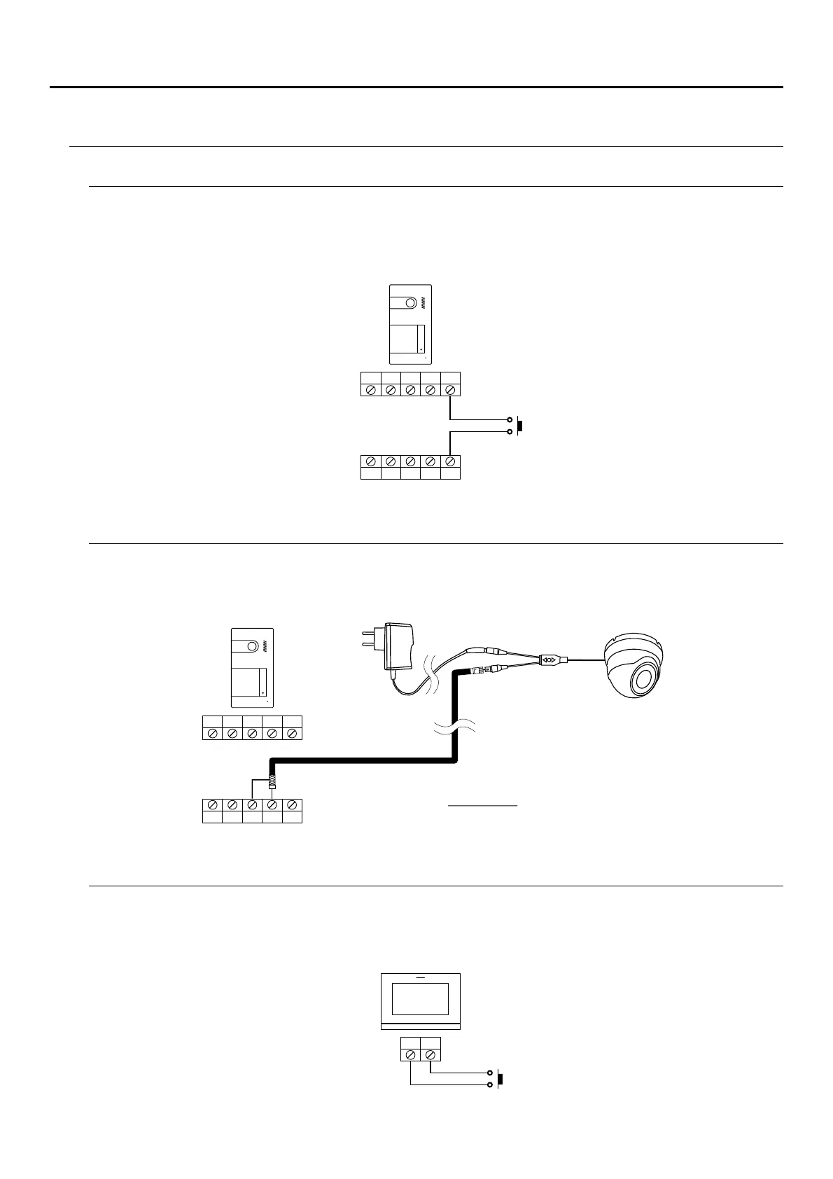
Connection of an output button
Connection of an external camera
Connection for an apartment door button
The output button allows remote activation of the lock release connected between the CV- and CV+ terminals
(by default) or the relay output (see pp. 39-41). The delay time in carrying out the activation is 2 seconds, with the
possibility of setting it to between 0.5 and 10 seconds (see pp. 39-41).
It is possible to connect a Golmar AHD4-3601x analogue CCTV camera to each of the door panels, which can be
viewed (see pp. 39-41) from the monitor. The camera needs to have a local PSU-121 power supply.
Only connect the apartment door button to the master monitor of the apartment that will be receiving the call. The
signal received is then transmitted to the slave monitors in the same apartment.
CV-
GND
BUS
C
CV+
CCTV
AP+
AP-
BUS
NA
HZ HZ
CV-
GND
BUS
C
CV+
CCTV
AP+
AP-
BUS
NA
SOUL PANEL/1
SOUL PANEL/1
ART 7 /G2+W
Mains
110~240Vac
L
R
PSU-121 POWER SUPPLY
(Code 31690144)
AHD4-3601x ANALOGUE
(Code 31600144)CCTV CAMERA
Important: Set the camera with a CVBS analogue
signal, as described in the accompanying
AHD4-3601x camera manual.
JOYSTICK