SOUL S5110/ART 7W VIDEO DOOR ENTRY SYSTEM KIT
6
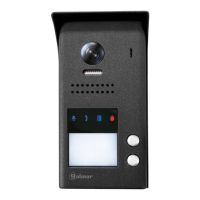
SOUL PANEL
Installation
The door panel has been designed to withstand diverse environmental conditions. It is however advisable to take
extra precautions to prolong its service life, such as locating it in a covered area.
For optimum image quality, avoid direct contact from light sources (sunshine, street lights, etc.).
1. Remove the metal front piece of the door panel by loosening the bottom screw with the Allen key supplied. On
the back of the front piece, you will find the button personalisation label.
2. Remove the screws that secure the proximity reader.
For correct installation: (locate the top of the door panel at a height of 1.65m).
3. Present the door panel to the wall, positioning the top at 1.65m. Pass the installation cables through the cable
grommet.
4. Drill three 6mm holes at the indicated points (M), see p. 5. Insert the plugs supplied and fix the door panel to the
wall using the screws supplied.
Before replacing the proximity reader and closing the door panel, make the necessary settings (proximity key
programming, audio level setting, etc.), as indicated throughout this manual. Make sure that the proximity
reader gasket is properly fitted.
5. Connect the cables to the removable terminals following the instructions in the installation diagrams.
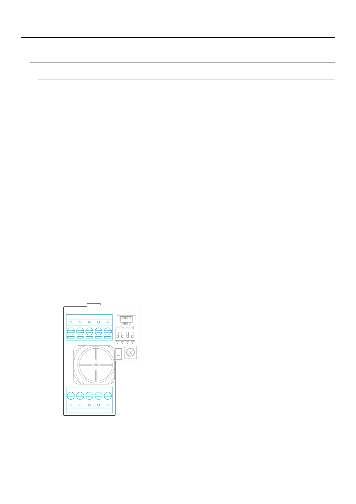
Installation terminals (O)
For ease of installation, the installation terminals are removable and supplied in a separate bag. Once the
terminals are wired, place them in position.
BUS BUS CV- CV+ AP+
C NA GND CCTV AP-
ON
1 2 3 4
GND CCTV, : input for external analogue camera.
BUS BUS, : communications bus (non-polarised).
CV CV-, +: lock release output 12Vdc (maximum 270mA).
AP AP+, -: remote activation button connection. Note: For correct
operation, the monitor's address 1 must be connected to
the Bus.
C, : potential-free relay output (maximum 6A/24V).NA