21
02 Installation Instructions User Manual V1.3-2021-12-15
[1] For batteries with attached switch, the external DC switch is not necessary.
[2] Only for lithium battery which has BMS communication.
[3] Direction of the CT cannot be connected in reverse, please follow "House > Grid" direction to
do the connection.
For Spain Grid code, the output max. apparent power of GW6000-BH is 6KVA and will be less
than
5kVA exported to grid limited by CT controller and power meter.
If the generation facility to be connected to the supply network with more than 5 kVA power in
single phase, connection of the facility to the network shall be three-phase with an imbalance
between phases of less than 5kW.
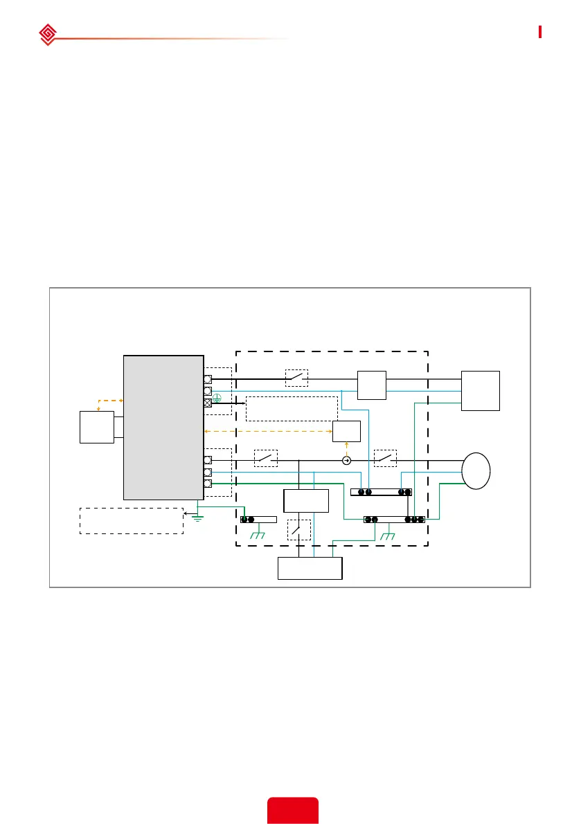
System connection diagrams
Note: According to australian safety country, the neutral cable of on-grid side and back-up side must be
connected together, otherwise back-up function will not work.
This diagram is an example for an application that neutral connects with the PE in a
distribution box.
For countries such as Australia, New Zealand, South Africa, etc., please follow local wiring
regulations!
Back-Up
PE
Meter
L
N
L
N
PE
L
N
PE
L
N
PE
E-N
Link
E-BAR
E-BAR
N-BAR
RS485
RCD
CT
On-Grid
RCD
BMS
Do not connect this terminal when
the neutral wire and PE wire are
connected together.
Grounding screw hole in
the lower right corner
Normal Loads
L
N
Battery
Hybrid Inverter
Distribution box
Backup
Loads
Grid
Smart
Meter
 Loading...