GMC-I Messtechnik GmbH 25
Setting Measuring Parameters for RPE
1
SECUTEST BASE10 (feature G01):
Measurement cannot be performed with 10 A AC for this measurement
type.
Entering and Deleting Offset Values
The test instrument determines protective conductor resistance
by means of a 4-pole measurement. If measurement cables or
extension cords are used whose ohmic resistance should be
automatically subtracted from the measurement results, there are
two ways to save the respective offset value in the R
PE
switch
position:
• Entry via the numeric keypad
• Acceptance of the momentary measured value by pressing the
SET OFFSET softkey
Proceed as follows in order to accept the measured value:
➭
Start the measurement and wait until the measured value settles in.
➭ Press the
SET OFFSET
key. The value is transferred to the offset
field.
The entered or accepted offset value is permanently stored and is
subtracted from all protective conductor resistance values mea-
sured in the future. This applies to single measurements as well
as to measurements conducted in the AUTO switch positions.
The symbol is displayed in the header in all switch positions
until the offset value is deleted by pressing the CLEAR OFFSET soft-
key (R
PE
switch position).
Test Sequence with Connection to the Test Socket
➭ Set the rotary switch to the R
PE
position.
➭ Select measurement type or connection type, and test cur-
rent. After pressing the Ip key, you have direct access to the
test current parameters: each time this key is pressed, the
setpoint value shown in the measuring window is switched to
the next value.
➭ Connect the DUT to the test socket.
➭ Start the test: press the START/STOP key.
➭ Contact all conductive parts which are connected to
the protective conductor with test probe P1.
During measurement, the connector cable must only be moved to
the extent to which it’s accessible during repair, modification or
testing.
If a change in resistance occurs during the manual test step of the
continuity test, it must be assumed that the protective conductor
is damaged, or that one of the connector contacts is no longer in
flawless condition.
➭ The measured values are displayed. The measured
value recording symbol shown at the right appears.
Each time this key is pressed, the currently displayed
measured value is saved to the buffer.
➭ Stop the test: press the START/STOP key.
The save symbol appears (floppy disk showing the
number of measured values stored to buffer memory)
and prompts you to save the measured values to an ID
number.
➭ Read the measured values and compare them with the
table of permissible limit values.
➭ Press the ESC key in order to discard the measured
values stored to buffer memory and acknowledge by
pressing the key shown at the right.
Special Case: Testing Extension Cords
➭
Set the measurement type parameter to “PE(TS) – P1”.
➭ Connect the EL1 adapter to the P1 sockets at the test instru-
ment.
➭ Connect the plug at the end of the extension cord to the test
socket.
➭ Connect the coupling socket at the end of the extension cord
to the plug at the EL1 adapter.
➭ Same test sequence as described above.
Further options for testing extension cords are included in the
description of single measurements in the EL1 switch position
and under automatic test sequences in switch position A8.
Special case: permanently installed DUT
➭ Contact all conductive housing parts with test probe P1.
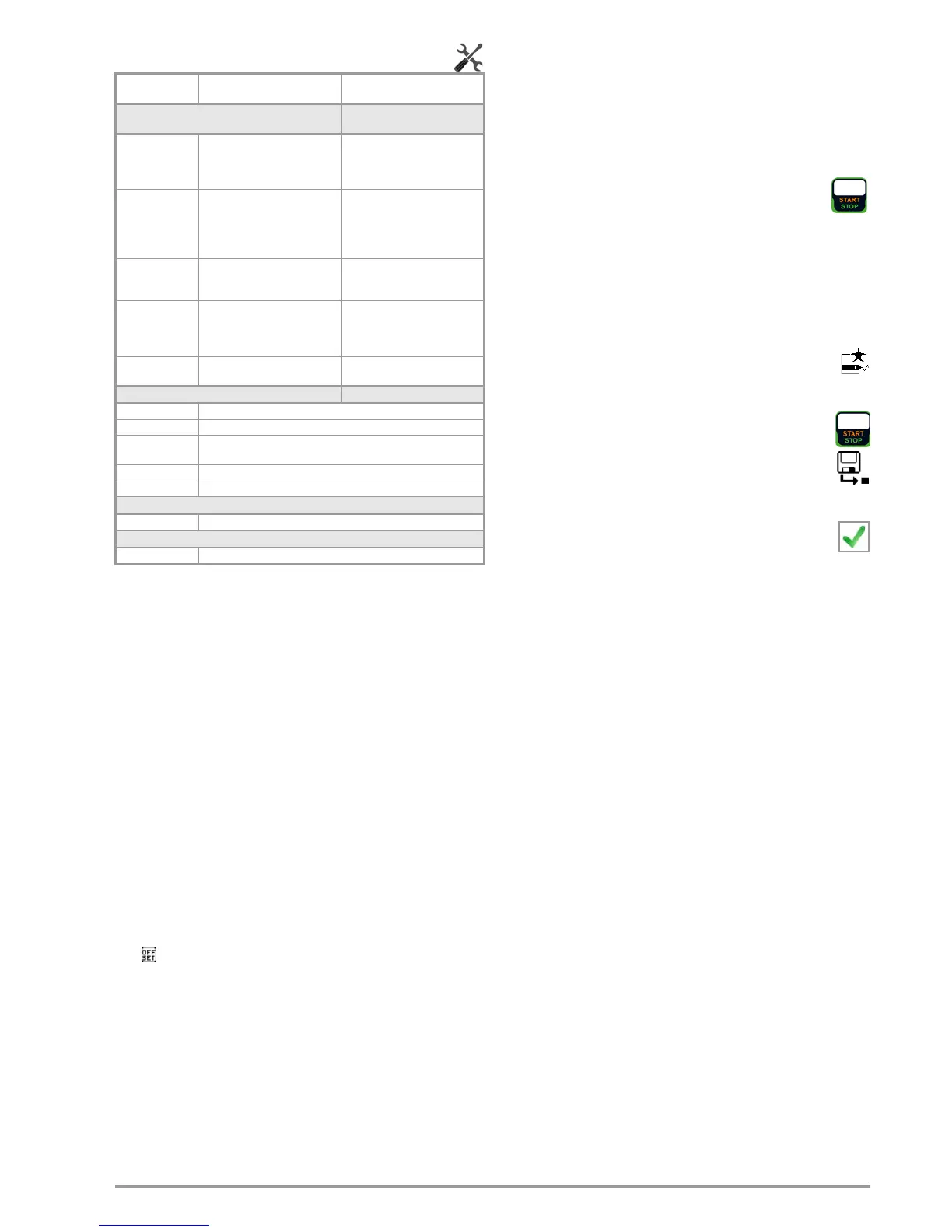
Measuring
Parameter
Meaning
Measurement Type,
Suitable for
DUT Connection via
(passive:) PE(TS)
– P1
Testing is conducted between the
two protective conductor terminals:
at the test socket and test probe
P1.
Test socket, EL1 with DUT at test
socket, VL2E, AT3 adapter (AT3-
IIIE, AT3-IIS, AT3-IIS32),
AT16DI/AT32DI
Active: PE(TS) –
P1
1
Same as PE(TS) – P1, but with
line voltage to the test socket,
200 mA AC flow immediately, as
well as continuously rising DC
test current (PRCDs)
Test socket (for PRCDs)
PE(mains) – P1
permanently con-
nected DUTs
Testing is conducted between the
ground terminal at the mains and
test probe P1.
Permanent connection
P1 – P2
SECUTEST PRO or feature H01:
2-pole measurement between
test probes 1 and 2 (see section
6.6)
Permanent connection
Clamp Test current measurement with
current clamp sensor
Permanent connection
IP(set)
+200 mA DC Test current: positive direct current
-200 mA DC Test current: negative direct current
±200 mA (DC) Test current: direct current whose polarity is reversed every 2 sec-
onds
200 mA (AC) Test current: alternating current
10 A (AC)
10 A test current:
SECUTEST BASE10
or
PRO
only (feature G01)
f – only at 200 mA (AC)
50 ... 200 Hz Test frequency
Offset
> 0 to < 2 Ω Zero balancing for a selected reference point.

 Loading...


