GMC-I Messtechnik GmbH 9
4.1.1 Measurements in IT Systems (new parameter as of firmware
1.5.0)
The IT system
setting can be
activated for all
single measure-
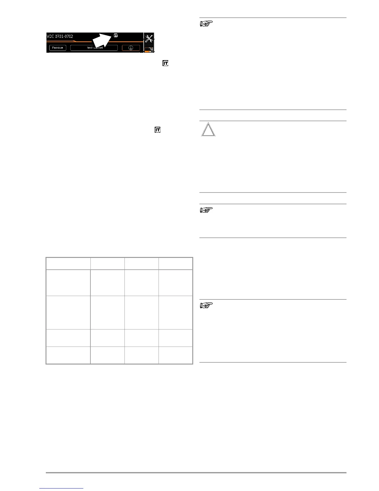
ments and test sequences in the SETUP switch position (Setup 1/
3) in the All measurements submenu (in this case the symbol
appears in the header of each display page):
With “Measurement at IT system” set to Yes: active leakage current
measurements (or all measurements with reference to PE at the
mains connection side) are disabled. Test sequences which
include measurements of this sort are also disabled.
If, when being connected to line voltage, the SECUTEST detects
a change at PE as compared with the previously used mains con-
nection, the user is asked directly after initial start-up if the cur-
rently used outlet belongs to an IT system. The IT system option
in SETUP is activated based on the user’s answer. If “Measurement
at IT system” is activated, this is indicated by the symbol in the
header. Regardless of this, it’s always possible to accordingly
change the option manually in SETUP.
The setting for the “Measurement at IT system” option is retained
even after disconnection from the mains.
Reliable measured values cannot be obtained from active leakage
current measurements (or from any measurements with reference
to PE at the mains connection side) in IT systems, for which rea-
sons all single measurements of this sort, as well as test
sequences which include this type of measurement, are disabled
when the “Measurement at IT system” option has been activated
in SETUP.
4.1.2 Automatic Recognition of Mains Connection Errors
The device automatically recognizes mains connection errors if
the conditions in the following table have been fulfilled. The user is
informed of the type of error, and all measuring functions are dis-
abled in the event of danger.
1
10 A R
PE
measurements are only possible with line voltages of 115/
230 V and line frequencies of 50/60 Hz.
2
If the user of the test instrument is too well insulated, the following error mes-
sage may appear: “Interference voltage at mains connection PE”
Finger Contact
During this test for correct mains connection, a voltage
measurement is performed between the finger contact
and PE at the test instrument’s mains connection, and its
reference potential is acquired via the user’s body resis-
tance to the conductive start key. In order to obtain reli-
able measurement results, this resistance value must be
less than 1 MΩ. If the user is wearing insulating shoes or
gloves, or is standing on an insulating floor covering,
erroneous measurements and display of the “Interference
voltage at mains connection PE” message may result. Try
to reduce resistance in this case, for example by touching
ground potential with the other hand (e.g. a radiator, but
not an insulating wall etc.).
If, while testing protective conductor potential, you deter-
mine that the mains protective conductor is conducting volt-
age (in accordance with the first two cases mentioned),
no further measurements may be performed with the test in-
strument. If this is the case, potentially dangerous voltage
is also present at the accessible earthing contacts of the
standard socket (test socket). Immediately disconnect
the test instrument from the mains and arrange to have
the fault eliminated at the mains connection.
Voltage at the electrical system’s protective conductor PE may
result in distorted measurement values during testing for
the absence of voltage, or during leakage voltage mea-
surements.
4.2 Connecting Test Probe P1 or P2
Insert the double plug from test probe P1 or P2 into socket 1 or 2
respectively such that the plug with the white ring makes contact
with the socket with the vertical bar.
The white ring identifies the terminal for the high current conduc-
tor which is safeguarded by the neighboring fuse link.
Difficultly in contacting exposed conductive parts when using
the standard probe with test tip
In order to assure good contact, surface coatings must
be removed from devices under test with special tools at
a suitable location.
The tip of test probe P1 is not suitable for scratching away
paint, because this may impair its coating and/or mechani-
cal strength. Brush probe Z745G may be more suitable than
the test probe in certain individual cases.
Type of Mains
Connection Error
Message Condition Measurements
Voltage at protective con-
ductor PE
to finger contact
(START/STOP key)
Display at the
instrument
Press START/STOP
button
U > 25 V
→ PE key:
< 1 MΩ
2
All measurements
disabled
Protective conductor PE
and phase
conductor L
reversed and/or
neutral conductor N
interrupted
Voltage at PE
> 100 V
Impossible
(no supply power)
Line voltage
< 180 V / < 90 V
(depending on mains)
U
L-N
< 180 V
U
L-N
<90V
Conditionally
possible
1
Test for IT/TN system
Display at the
instrument
Connection
N → PE
> 50 kΩ
Possible under
certain circum-
stances

 Loading...


