8 GMC-I Messtechnik GmbH
3.5.3 Printing via ETC
Alternatively, stored measurement data can be read into ETC
report generating software at a PC and printed out as a report.
3.6 Print-Out of Barcodes (as of firmware V1.3.0)
A barcode printer allows for the following applications:
• Print-out of ID numbers as barcodes for devices under test,
encrypted – for quick and convenient acquisition during peri-
odic testing
• Print-out of repeatedly occurring designations such as test
object types encrypted as barcodes in a list, allowing them to
be read in as required for comments.
We are unable to offer any guarantees regarding the use
of printers other than those listed in the appendix.
If you have connected a suitable barcode printer (see list in
appendix in section 14.1) via the USB master port, you can print
out a barcode for each device under test by pressing the PRINT
key.
➭ By viewing the printer information, you can first of all deter-
mine whether or not the connected barcode printer is cor-
rectly recognized by the test instrument: Setup (2/3) > Printer
> Z721D > Printer information
➭ Select the desired paper (the current tray in the Z721D) and
coding under setup: Setup (2/3) > Printer > Z721D > Printer
settings
➭ Change to the database view (MEM key).
➭
Select the desired device under test with the scroll keys.
➭ Press the PRINT key.
➭
The ID is printed out as a barcode and as text. An error message
appears if the ID cannot be converted to a barcode.
3.7 Writing RFID Tags
(as of firmware V1.5.0 with option for database expansion)
The following function is made possible by an RFID scanner
(writer):
• Read-out of encrypted ID numbers for devices under test to
an RFID tag for quick and convenient read-in during periodic
testing
If you have connected a suitable RFID scanner (see list in appen-
dix in section 14.1) via the USB master port, you can write an
RFID tag for each device under test by pressing the PRINT key:
➭ Correct recognition of the RFID scanner by the test instrument
after connection to the USB port is indicated by the icon in
the header.
➭ Change to the database view (TMEM key).
➭ Select the desired device under test with the scroll keys or
enter a new device under test by means of its ID.
➭
Briefly press the
PRINT
key on the test instrument.
➭ You are prompted to hold the scanner at a distance of about
3 cm directly in front of the middle of the RFID tag.
The “Successful write” message appears to indicate that the pro-
cedure has been completed.
An error message appears if the ID cannot be converted
to an RFID tag.
We are unable to offer any guarantees regarding the use
of readers or writers other than those listed in the appen-
dix.
3.8 Saving Reports to a USB Flash Drive (only with SECUTEST
PRO or instruments with feature KB01)
Select a measurement from the database view (MEMkey) with the
scroll keys, for which a report will be saved to a USB flash drive.
Then press the PRINT key. “Print job finished” appears. The report
is written to a BMP file.
4 Initial Start-Up
4.1 Connecting the Test Instrument to the Mains
➭ See section 12 for nominal mains values (nominal ranges of
use).
➭ Connect the test instrument to the mains cable via its inlet
plug and insert the mains plug into an electrical outlet. The
function selector switch can be set to any position.
If a mains outlet (earthing contact outlet) is not available, or if
only a 3-phase outlet is available, the adapter socket can be
used to connect the phase conductor, the neutral conductor
and the protective conductor. The adapter socket has three
permanently attached cables and is included with the KS13
cable set.
If connection is not possible via an earthing contact out-
let: Shut down mains power first.
Then connect the cables from the coupling socket to the
mains using pick-off clips in accordance with the dia-
gram. Disconnection from mains power is only possible
with the mains plug.
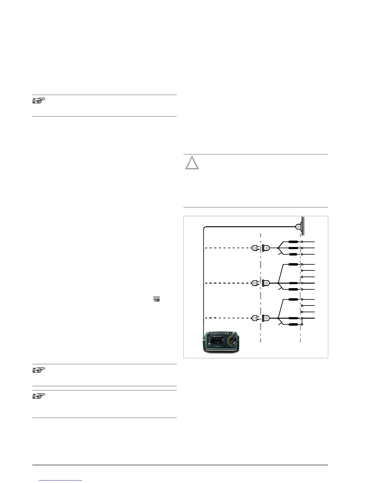
Figure 1: Connecting the Test Instrument to the Mains
L1
N
Green-yellow
Green-yellow
PE
L1
L2
L3
N
PE
L1
L2
L3
N
Green-yellow
KS13

 Loading...


