GMC-I Messtechnik GmbH 35
8.7.2 Touch Current – IB
Applications
Make sure that the contacted parts are not grounded.
Definition
Current which flows from housing parts which are not connected
to the protective conductor via an external conductive connection
to earth or another part of the housing. Flow of current via the
protective conductor is excluded in this case.
The following designations are also common:
housing leakage current, probe current.
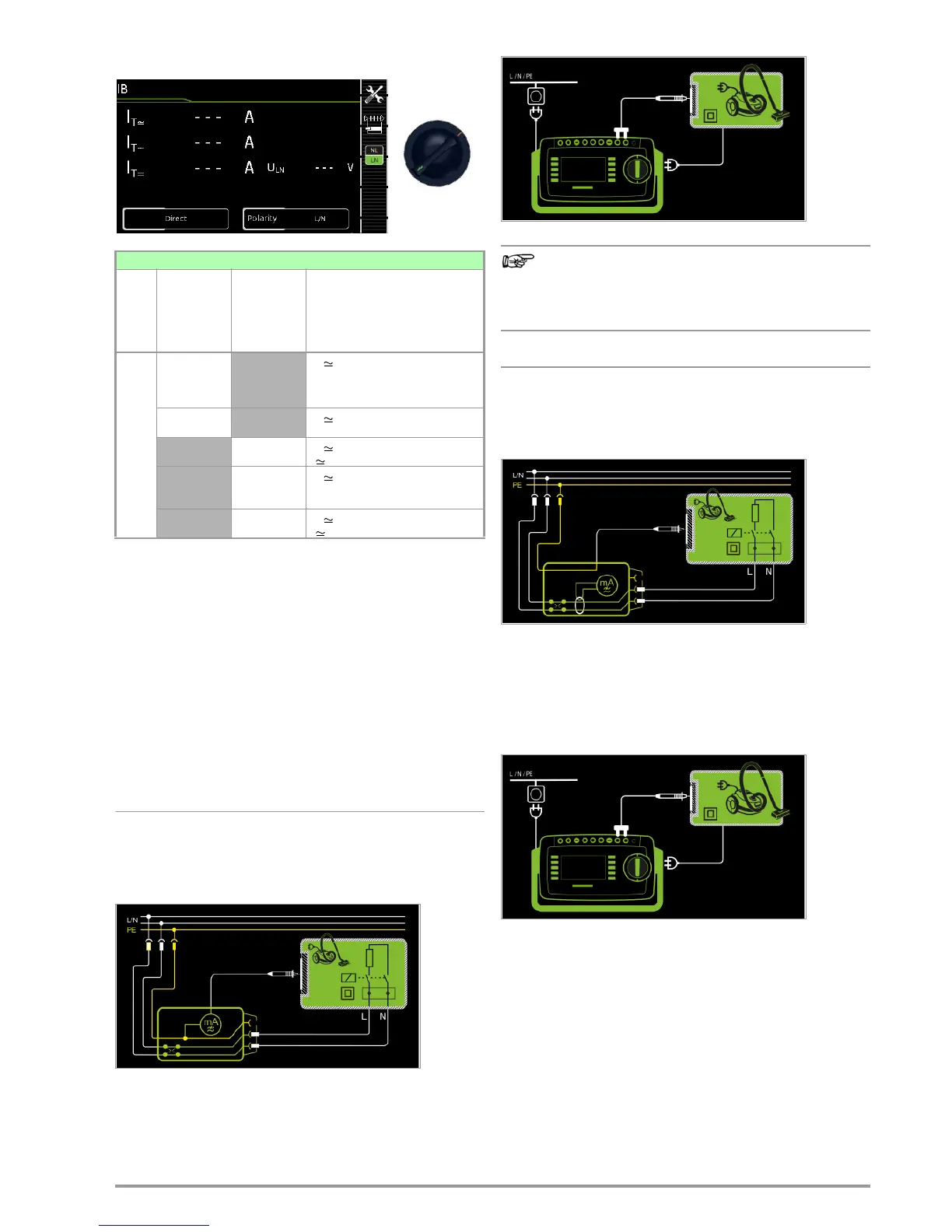
Direct Measuring Method
– Direct measurement type
– DUT mains plug to test socket
– Test probe P1 to P1 terminals
Schematic Diagram
The device under test is operated with mains power. Current
which flows to the protective conductor via exposed conductive
parts is measured by means of the probe. The measurements
must be performed with mains plug polarity in both directions.
Polarity is reversed with the NL/LN key. The RMS, the AC or the
DC component of the current is measured.
Wiring Diagram
regarding protection class I DUTs:
Parts may or may not be grounded.
Coincidental grounding only occurs in the event of an
error.
Differential Current Method
– Differential measurement type
– DUT mains plug to test socket
– Test probe P1 to P1 terminals
Schematic Diagram
The device under test (PC2) is operated with mains power. Differ-
ential current which flows via the two mains conductors is mea-
sured (current clamp measurement concept). The measurements
must be performed with mains plug polarity in both directions.
Polarity is reversed with the NL/LN key. The current’s AC compo-
nent is measured. Accessible conductive parts must be con-
tacted with test probe P1.
Wiring Diagram
Single measurements, rotary switch level: green
Switch
Position
Measure-
ment Type,
With Mains
to Test
Socket
Measure-
ment Type,
Without
Mains
to Test
Socket
Measuring Functions
I
C
Direct
I
B
Touch current, RMS
I
B~
AC component
I
B=
DC component
U
LN
Test volt age
Differential
I
B
Touch current, RMS
U
LN
Test volt age
Alternative (P1)
I
B
Touch current, RMS
U Test voltage
Permanent
connection
I
B
Touch current, RMS
I
B~
AC component
I
B=
DC component
Alternative
(P1–P2)
I
B
Touch current, RMS
U Test voltage

 Loading...


