GMC-I Messtechnik GmbH 55
10.3 Connecting the DUT
➭ Connect the DUT to the test instrument in accordance with
the selected test sequence.
– Test socket
– Permanent connection
– Adapter
Switch position: A1 ... A7, AUTO
Connection depends on the type of DUT (see the respective con-
nection type in the classification parameters tables).
Switch position A8
For testing extension cords in accordance with standards: con-
nection to the test socket via the following adapter:
– EL1: for single-phase extension cords
– VL2E:
for single and 3-phase extension cords
10.4 Selecting a DUT
➭ If no DUT has been selected in the initial display, enter its ID
number, for example by means of a barcode scanner, after
selecting ID.
➭
As an alternative
, activate the database view with the
MEM key:
➭ Select the DUT for the test sequence with the scroll keys.
➭ Return to the measuring view by pressing the MEM key.
10.5 Checking Connection and Starting the Test Sequence
➭ Trigger the connection test and the test sequence
by pressing the START key.
The following checks are run automatically before the
test sequence is started:
•Probe test
(whether or not test probe P1 is connected)
• Insulation test (whether or not the DUT is set up in a well-insu-
lated fashion)
• On test and short-circuit test
(prerequisite: “short-circuit test L-N” sequence parameter is
preset to “on”.
In order to be able to detect a short-circuit at the DUT, testing
is conducted between L and N, as well as LN and PE.
If you deselect important test steps under sequence param-
eter (set to off), the test sequence might not fulfill the require-
ments stipulated by the standard any more.
If you have set the “
Detected classification
” parameter for the
respective test sequence to “Always accept” and the “
Auto-
detection of
” parameter to “
Connection and PC
” (before trig-
gering Start), the following additional checks will be run
before the test sequence is started:
• Protection class detection for DUTs with protective conductor
• Connection check: whether or not the DUT is connected to
the test socket. In the case of protection class I: whether or
not the two protective conductor terminals are short-circuited.
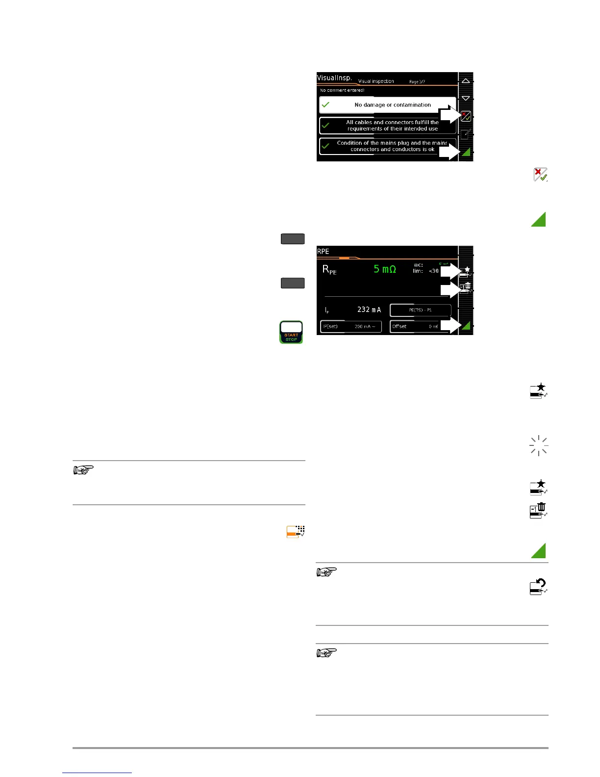
10.6 Executing and Evaluating Test Steps
Manual Evaluation of Visual Inspection
(prerequisite: “visual inspection” sequence parameter is preset to
“on”.
➭ Evaluate the visual inspection.
➭ If you mark even one visual inspection as not passed
with the key shown at the right, the sequence is aborted and
the test is evaluated as not passed.
➭ Resume the test sequence.
Test Steps with Manual Evaluation (e.g. R
PE
)
➭ Observe instructions which appear at the display, e.g.
prompting to contact parts with test probe P1.
If the measured value appears green at the display, it lies within
the limits specified by the standard.
➭ The measured value recording symbol appears in the
softkey bar. The 0 indicates that no measured values
have thus far been saved to buffer memory.
➭ Each time this key is pressed, the measuring or evaluation
procedure is restarted.
➭ Initially, the digit blinks (here a 1 without symbol) until
the measured value settles in. The evaluation cycle is
visualized as follows: the progress bar starts at the left-
hand edge of the display and moves to the right. When
it reaches the rightmost position, evaluation has been
completed and the symbol shown at the right appears
with the current number.
➭ Depending on whether you want to delete the last
value saved to the clipboard or all values, press the
symbol with the wastebasket shown at the right an ap-
propriate number of times.
➭ Proceed to the next measurement by pressing the key
shown at the right.
Regarding the test sequence in switch position A6/A7:
Section 5.2 of DIN EN 90974-4 expressly stipulates that
the cables have to be bent and twisted over their entire
length during the measurement, in particular in proximity
to the cable glands, in order to be able to detect any
interruptions of the protective conductor.

 Loading...


