38 GMC-I Messtechnik GmbH
8.7.3 Device Leakage Current – IG
1
Adapter
AT3-IIIE,
AT3-IIS or AT3-II S32:
Voltage measuring inputs for leakage current measurement with differ-
ential method with SECUTEST PRO only (or instrument with feature I01)
2
Voltage measuring inputs for leakage current measurement with differ-
ential method using the WZ12C current clamp sensor, with SECUTEST
PRO only (or instrument with feature I01)
Applications
Measurement of device leakage current is required for electrical med-
ical devices in accordance with IEC 62353 (VDE 0751-1).
In the case of device leakage current as the sum of all leakage cur-
rent, all probe contact points must be contacted simultaneously.
Definition
Device leakage current is the sum of all leakage currents from the
housing, accessible conductive parts and applied parts to PE.
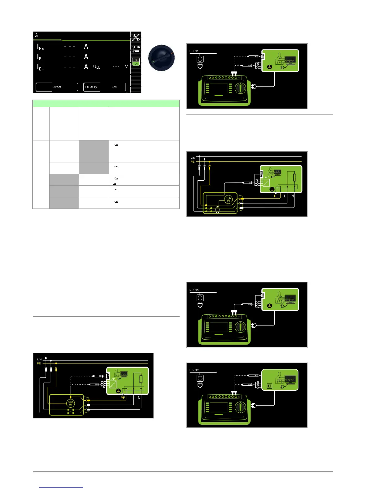
Direct Measuring Method
– Direct measurement type
– DUT mains plug to test socket
– Test probe P1 to P1 terminals
Schematic Diagram
The device under test (PC1) is operated with mains power.
Protective conductor current is measured between the protective
conductor at the mains (test instrument supply power) and the
protective conductor terminal at the DUT via the DUT’s mains
cable. The measurements must be performed with mains plug
polarity in both directions. Polarity is reversed with the NL/LN key.
Accessible conductive parts which are connected to the housing,
as well as those which are not connected to the housing, must be
contacted with test probe P1.
If the DUT includes terminals for applied parts, they must be
short-circuited and contacted with test probe P1 as well.
Wiring Diagram
Differential Current Measurement
– Differential measurement type
– DUT mains plug to test socket
– Test probe P1 to P1 terminals
Schematic Diagram, Protection Class I
The device under test (PC1) is operated with mains power.
Differential current which flows via the two mains conductors is
measured (current clamp measurement concept). The measure-
ments must be performed with mains plug polarity in both direc-
tions. Polarity is reversed with the NL/LN key.
Short-circuited terminals for applied parts or accessible conduc-
tive parts which are not connected to the housing must be con-
tacted with test probe P1.
Wiring Diagram, Protection Class I
Wiring Diagram, Protection Class II
Single measurements, rotary switch level: green
Switch
Position
Measure-
ment Type,
With Mains
to Test
Socket
Measure-
ment Type,
Without
Mains
to Test
Socket
Measuring Functions
I
G
Direct
I
G
Device leakage current, RMS
I
G~
AC component
I
G=
DC component
U
LN
Test volt age
Differential
I
G
Device leakage current, RMS
U
LN
Test volt age
Alternative
I
G
Device leakage current, RMS
U Test voltage
AT3 adapter
1
I
G
Device leakage current, RMS
U
LN
Test volt age
Clamp
2
I
G
Device leakage current, RMS
U
LN
Test volt age

 Loading...


