42 GMC-I Messtechnik GmbH
Setting Measuring Parameters for IA
Test Sequence
➭ Set the rotary switch to the I
A
position.
➭ Connect the DUT in accordance with the selected measuring
method.
➭ Set the parameters:
Select the Direct or Alternative measurement type:
➭ In the case of direct measurement, measurement must
be performed with mains plug polarity in both direc-
tions. Select the respective polarity to this end by
pressing the NL/LN key.
➭ Start the test: press the START/STOP key.
➭ After each reconnection to the mains, and as soon as
the first test is started, a mains connection test is exe-
cuted.
➭ In the case of the direct measurement type (P1): acknowl-
edge the warning which indicates that line voltage will
be connected to the test socket.
➭ Contact the short-circuited applied parts with the test probe.
➭ The measured values are displayed. The measured
value recording symbol shown at the right appears.
Each time this key is pressed, the currently displayed
measured value is saved to the buffer.
➭ Stop the test: press the START/STOP key.
The save symbol appears (floppy disk showing the
number of measured values stored to buffer memory)
and prompts you to save the measured values to an ID
number.
➭ Read the measured values and compare them with the
table of permissible limit values.
➭ Press the ESC key in order to discard the measured
values stored to buffer memory and acknowledge by
pressing the key shown at the right.
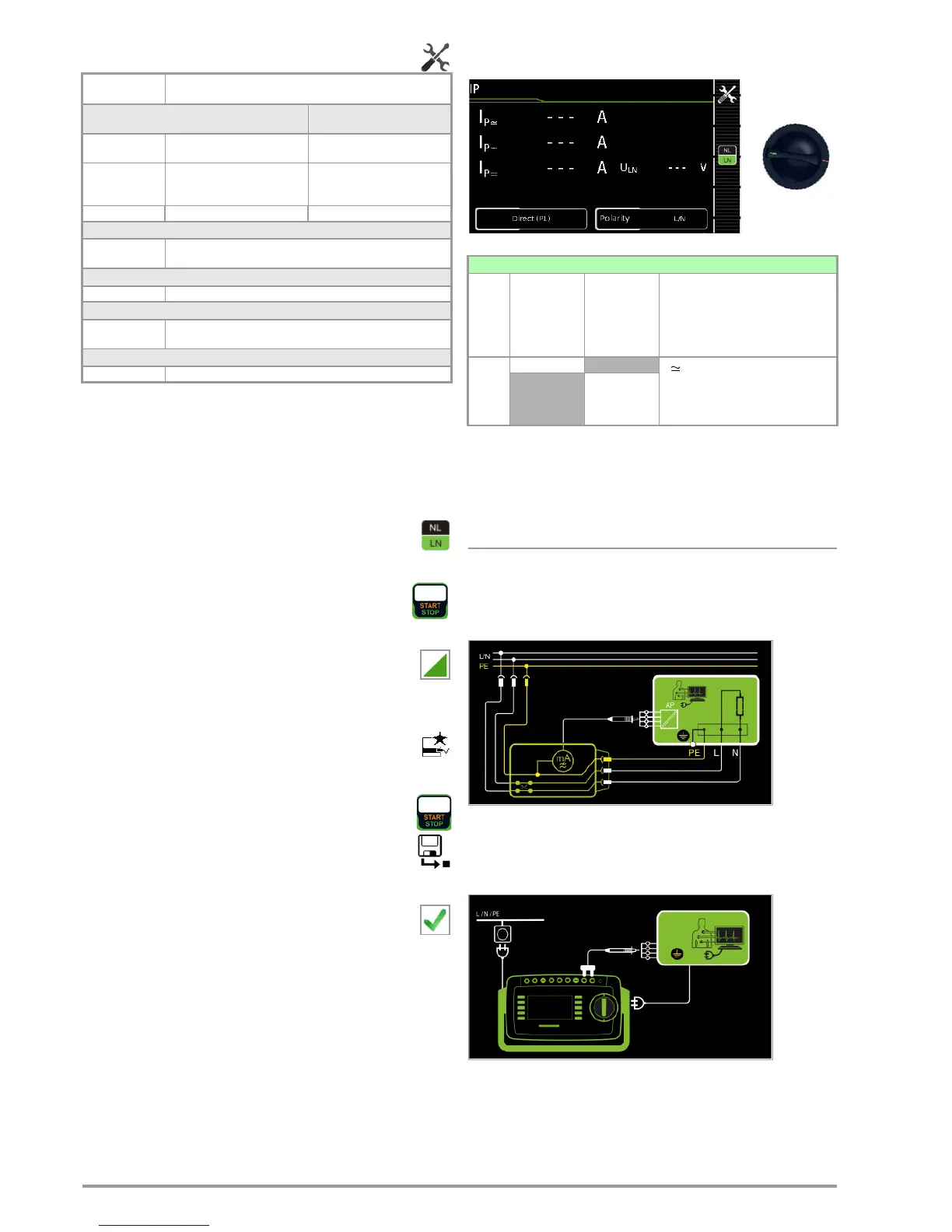
8.7.5 Patient Leakage Current – IP
Definition
Patient leakage current is the current which flows to ground or PE
from the patient ports at the running device via the patient.
The AC and the DC component of the current is measured.
Direct Measuring Method
– Direct measurement type (P1)
– DUT mains plug (PC1) connected to test socket
– Probe to P1 terminal
Schematic Diagram
After activating test voltage, patient leakage current is measured
at the DUT between PE (DUT mains plug) and the short-circuited
application parts.
Wiring Diagram
Measuring
Parameter
Meaning
Measurement Type,
Suitable for
DUT Connection via
Direct (P1) Direct measuring method (via
test socket) with test probe P1
Test socket
Alternative (P1) Equivalent leakage current mea-
suring method (via test socket)
with test probe P1
Test socket
Perm. con. (P1) Direct measuring method Permanent connection
Phase angle – for direct (P1) and permanent connection (P1) only
0 ° or 180 ° Selectable phasing for the internal generator relative to mains phas-
ing
Polarity – for direct only (P1)
L/N or N/L Selection of polarity for mains voltage to the test socket
U(set) – for alternative (P1) and permanent connection (P1) only
110 V, 115 V,
220 V, 230 V, 240 V
Selection of a line voltage for synthetic test voltage
Frequency(set) – for alternative only (P1)
48 Hz ... 400 Hz
Selection of a line frequency for synthetic test voltage
Single measurements, rotary switch level: green
Switch
Position
Measure-
ment Type,
With Mains
to Test
Socket
Measure-
ment Type,
Without
Mains
to Test
Socket
Measuring Functions
I
P
Direct (P1) I
P
Patient leakage current, RMS
I
P~
AC component
I
P=
DC component
U
LN
Test v olt age
Permanent
connection
(P1)

 Loading...


