GMC-I Messtechnik GmbH 3
Overview of Features Included with
SECUTEST BASE(10) and PRO Test Instruments
1
10 A R
PE
measurements are only possible with line voltages of 115/
230 V and line frequencies of 50/60 Hz.
2
Voltage measuring inputs with SECUTEST PRO only (or instrument with
feature I01)
3
Connection for 2
nd
test probe for 2-pole measurement with SECUTEST
PRO only (or instrument with feature H01)
4
Measurement of time to trip is not possible in IT systems.
Key
Alternative = alternative measurement (eq. leakage current meas.)
Differential = differential current measurement
Direct = direct measurement
LN(TS) = short-circuited L and N conductors at test socket
P1 = measurement with test probe P1
P1-P2 = 2-pole measurement with test probes P1 and P2
PE-P1 = measurement between PE and test probe P1
PE(TS) = protective conductor at the test socket
PE(mains) = protective conductor at the mains connection
Differences with Regard to Included Features
* For voltage measurement or for connecting a WZ12C current clamp or
an AT3 adapter, and for temperature measurement via RTD
Scope of Delivery
Standard Version (country-specific)
1 SECUTEST BASE(10) or PRO test instrument
1 Mains power cable
1 Test probe, 2 m, not coiled
1 USB cable, USB A to USB B, 1.0 m long
1 Plug-on alligator clip
1 KS17-ONE cable set for voltage measuring input
(only with
SECUTEST PRO
or instrument with feature I01)
1 Calibration certificate
1 Condensed operating instructions
1 Comprehensive operating instructions available on the Inter-
net
1 ETC report software available on the Internet
The most up-to-date version of ETC report generating software
can be downloaded free of charge from the mygmc page of our
website as a ZIP file, if you have registered your test instrument:
http://www.gossenmetrawatt.com
→ Products → Software → Software for Testers
→
Report Soft-
ware without Database
→
ETC
→
myGMC
The following must be observed if other software packages are
used: ETC report generating software must first be in-
stalled to the PC in order to be able to read out data with
the help of other software packages such as PC.doc-
WORD/EXCEL, PC.doc-ACCESS, ELEKTRO manager and PS3.
Switch
Position
Measuring Function
Test Current/Voltage
Measurement
Type, Connection
Type
Single measurements, rotary switch level: green
R
PE
Section
8.5
R
PE
Protective conductor resistance PE(TS) - P1 passive
PE(TS) - P1 active
PE(mains) - P1
PE(mains) - P1 clamp
2
P1–P2
3
I
P
Test current (200 mA)
SECUTEST BASE10/PRO: 10 A
1
(feature G01)
RISO
Section
8.6
R
ISO
Insulation resistance (PC I/PC II)
LN(TS) - PE(TS)
LN(TS) - P1
P1–P2
3
PE(mains) - P1
PE(TS) - P1
LN(TS) - P1//PE(TS)
U
ISO
Test volt age
IPE
Section
8.7.1
I
PE
Protective conductor current, RMS Direct
Differential
Alternative
AT3-Adapter
2
Clamp
2
I
PE~
AC component
I
PE=
DC component
U
LN
Test volt age
IB
Section
8.7.2
I
B
Touch current, RMS Direct
Differential
Alternative (P1)
Perm. connection
Alternative (P1–P2)
I
B~
AC component
I
B=
DC component
U
LN
Test volt age
IG
Section
8.7.3
I
G
Device leakage current, RMS Direct
Differential
Alternative
AT3-Adapter
2
Clamp
2
I
G~
AC component
I
G=
DC component
U
LN
Test volt age
IA
Section
8.7.4
I
A
Leakage current from the applied part, RMS
Direct (P1)
Alternative (P1)
Perm. con. (P1)
U
A
Test volt age
IP
Section
8.7.5
I
P
Patient leakage current, RMS
Direct (P1)
Perm. con. (P1)
I
P~
AC component
I
P=
DC component
U
LN
Test volt age
U
Section
8.9
U
Probe voltage, RMS
P1–P2
P1–P2 (with mains*)
* Polarity param.
U
~
Alternating voltage component
U
=
Direct voltage component
U
Measuring voltage, RMS
2
V – COM
V – COM (with mains)
U
~
Alternating voltage component
2
U
=
Direct voltage component
2
ta
4
Section
8.10
ta
PRCD time to trip for 30 mA PRCDs
U
LN
Line voltage at the test socket
P
Section
8.11
Function test at the test socket
Polarity parameter
I Current between L and N
U Voltage between L and N
f Frequency
P Active power
S Apparent power
PF Power factor
Probe Measuring Functions
EL1
Section
8.12
Extension cord with adapter: continuity, short-circuit,
polarity (wire reversal)
EL1 adapter
AT3-IIIE adapter
VL2E adapter
EXTRA
Section 9
Reserved for expansion during the course of software updates
°C Temperature measurement
2
with Pt100 /
Pt1000
V – COM
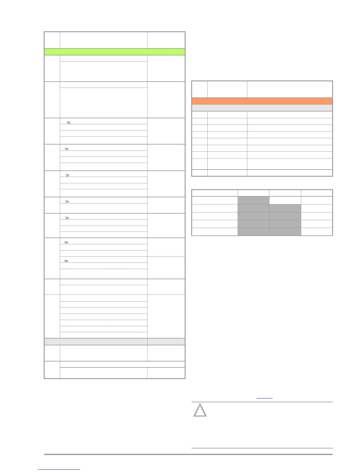
Switch
Position
Standard Measurement Type, Connection Type
Automated test sequences, rotary switch level: orange
Preconfigured (freely adjustable) test sequences – default settings
A1
VDE 0701-0702
Passive measurement type, test socket
A2
VDE 0701-0702
Active measurement type, test socket
A3
VDE 0701-0702-EDV
Parametrization for EDP (active)
A4
IEC 62353
(VDE 0751)
Active measurement type
A5
IEC 62353
(VDE 0751)
Active measurement type
A6
IEC 60974-4
Connection type: test socket
A7
IEC 60974-4
Connection type: AT16-DI/AT32-DI
A8
VDE 0701-0702
Extension cord measurement type
(RPE, RISO), adapter:
EL1
/VL2E/
AT3-IIIE
AUTO
VDE 0701-0702
Active measurement type, test socket
Feature SECUTEST BASE
SECUTEST BASE10
SECUTEST PRO
10 A RPE test current
••
Touch-screen keyboard
•
2
nd
test probe
•
Voltage meas. inputs *
•
Database expansion
•

 Loading...


