34 GMC-I Messtechnik GmbH
Test Sequence with Differential Current Method
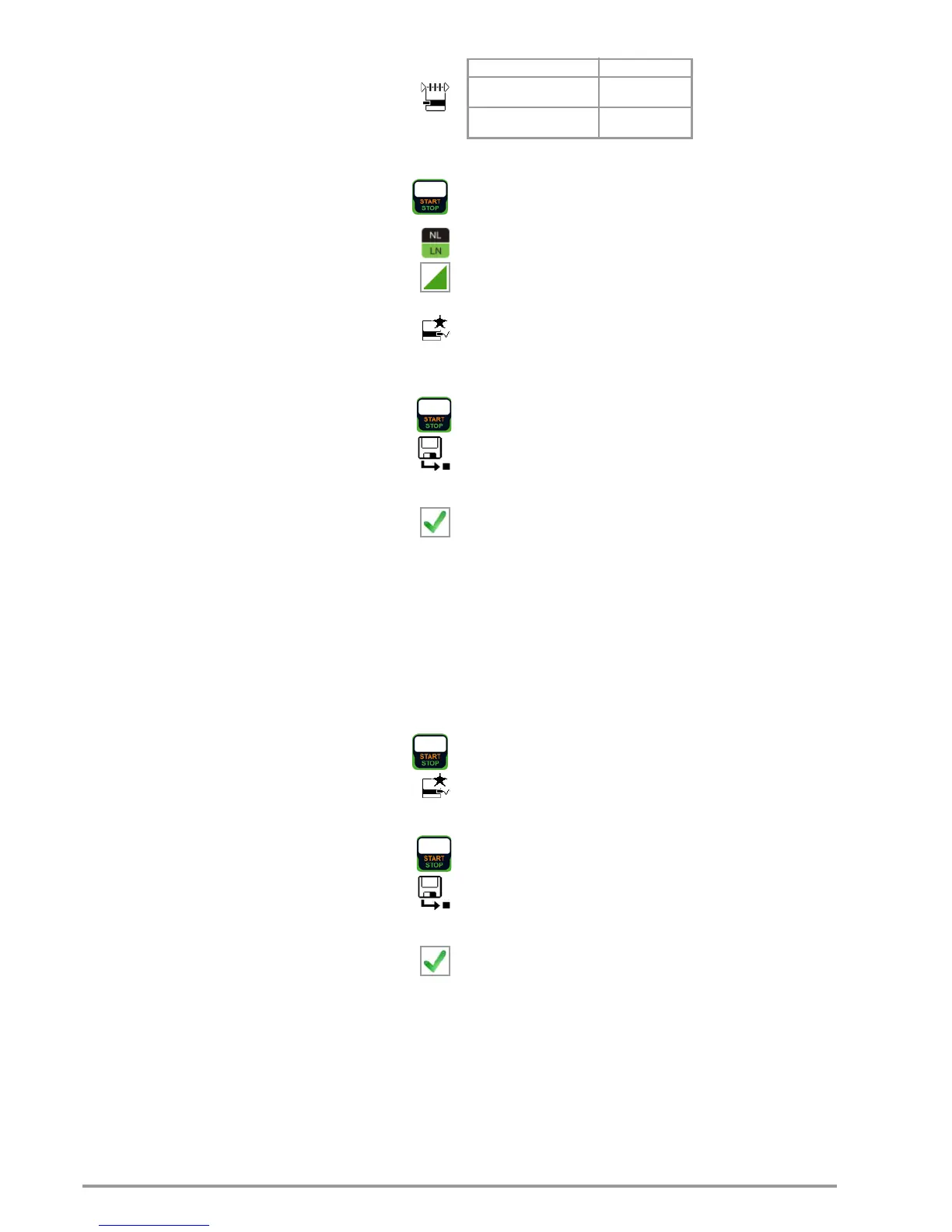
➭ Set the rotary switch to the I
PE
position.
➭ Select the Differential measurement type:
– By setting the parameters
or
– Directly by pressing the key shown at the right
➭ Connect the DUT’s mains plug (protection class I) to the test
instrument’s test socket.
➭ Start the test: press the START/STOP key.
➭ The measurement must be performed with mains plug
polarity in both directions by pressing the NL/LN key.
➭ Acknowledge the warning which indicates that line
voltage will be connected to the test socket.
➭ Switch the device under test on.
➭ The measured values are displayed. The measured
value recording symbol shown at the right appears.
Each time this key is pressed, the currently displayed
measured value is saved to the buffer.
➭ Turn off the device under test.
➭ Stop the test: press the START/STOP key.
The save symbol appears (floppy disk showing the
number of measured values stored to buffer memory)
and prompts you to save the measured values to an ID
number.
➭ Read the measured values and compare them with the table
of permissible limit values.
➭ Press the ESC key in order to discard the measured
values stored to buffer memory and acknowledge by
pressing the key shown at the right.
Test Sequence for Alternative Measuring Method
➭ Set the rotary switch to the I
PE
position.
➭ Select the Alternative measurement type:
– By setting the parameters
or
– Via the MA key
➭ Set the Up(set) and frequency parameters.
➭ Connect the DUT’s mains plug (protection class I) to the test
instrument’s test socket.
➭ Start the test: press the START/STOP key.
➭ Switch the device under test on.
➭ The measured values are displayed. The measured
value recording symbol shown at the right appears.
Each time this key is pressed, the currently displayed
measured value is saved to the buffer.
➭ Stop the test: press the START/STOP key.
The save symbol appears (floppy disk showing the
number of measured values stored to buffer memory)
and prompts you to save the measured values to an ID
number.
➭ Read the measured values and compare them with the table
of permissible limit values.
➭ Press the ESC key in order to discard the measured
values stored to buffer memory and acknowledge by
pressing the key shown at the right.
Maximum Permissible Limit Values for Leakage Current in mA
* For devices with heating power of greater than 3.5 kW
Note 1: Devices which are not equipped with accessible parts that are
connected to the protective conductor, and which comply with
requirements for touch current and, if applicable, patient leakage
current, e.g. computer equipment with shielded power pack
Note 2: Permanently connected devices with protective conductor
Note 3: Portable X-ray devices with mineral insulation
Key
I
PE
Current in the protective conductor (primary leakage current)
Test Standard I
PE
VDE 0701-0702:2008
PC I: 3.5
1 mA/kW *
DINEN60974-4
VDE 0544-4:2009-06
5 mA

 Loading...


