32 GMC-I Messtechnik GmbH
Wiring Diagram
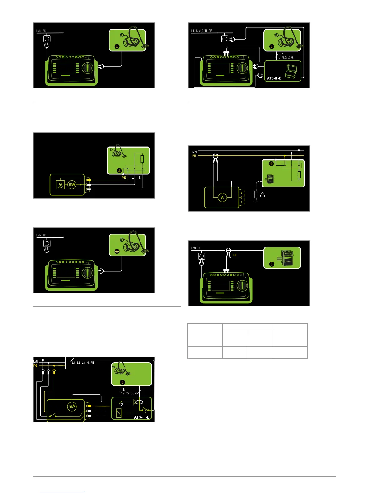
Alternative Measuring Method (equivalent leakage current)
– Alternative measurement type
– DUT mains plug (protection classes I) to test socket
Schematic Diagram
After activating test voltage, leakage current is measured via the
DUT’s mains cable between short-circuited mains conductors L
and N and the protective conductor terminal at the DUT.
Wiring Diagram
Connection of 3-phase DUTs (only with SECUTEST PRO or feature
I01 with optional test adapter AT3-IIIE)
– AT3-Adapter measurement type
– DUT mains plug to AT3-IIIE test adapter
– AT3-IIIE probe to COM-V terminals
– AT3-IIIE test plug to test socket
Schematic Diagram
Measurement of the DUT with 3-phase mains connection via
AT3-IIIE adapter
Wiring Diagram (AT3-IIIE probe to COM-V)
Measurement of protective conductor current via current clamp
sensor with voltage output for permanently installed DUTs (only
with SECUTEST PRO or feature I01 with optional WZ12C current
clamp sensor)
– Clamp measurement type
Schematic Diagram
Measurement of protective conductor current by closing the cur-
rent clamp sensor around mains PE for permanently installed pro-
tection class I devices under test
Wiring Diagram (WZ12C an COM-V)
Set Measuring Range at WZ12C and at the SECUTEST PRO
SECUTEST PRO
WZ12C clamp meter SECUTEST PRO
Transformation
Ratio
Parameter
Switch Measuring
Range
Display Range
with Clamp
1:1
1 V / A
1 mV / mA 1 mA ... 15 A 0 ... 300 A

 Loading...


