9
8
7
6
5
4
2
1
CF-9 User's Guide
09/30/92 GPD Global 5
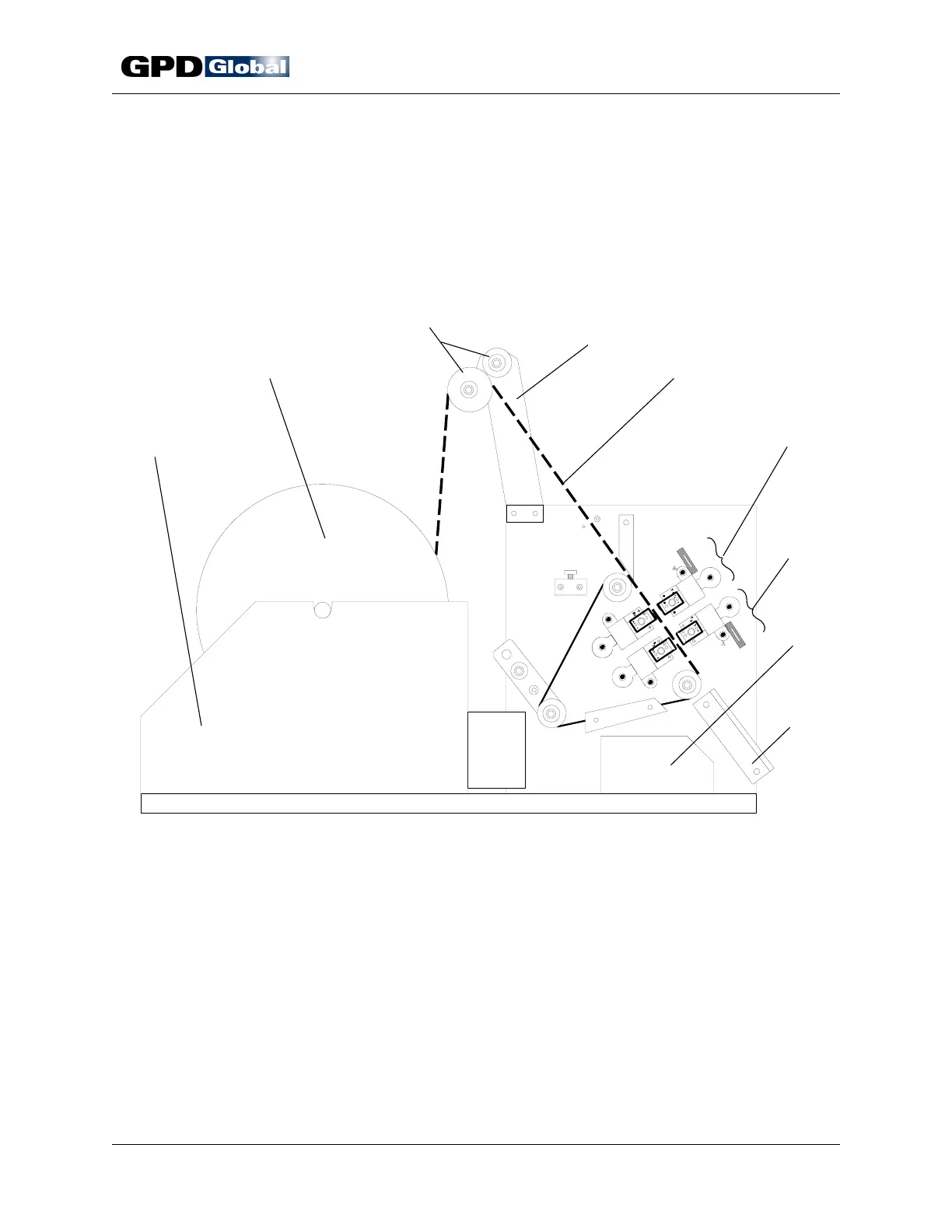
Figure 1 Principal Parts
Machine Part Identification
The CF-9's principal machine and die elements are identified and illustrated in this section.
Information for elements not defined elsewhere is also included here.
Principal Parts
Item 1 Reel Holder Item 6 Die Block Assembly, Station 1
Item 2 Component Reel / Ammo Pack Item 7 Die Block Assembly, Station 2
Item 3 Tape Roller Guide Item 8 Component Bin
Item 4 Tape Guide Arm Item 9 Tape Exit Chute
Item 5 Taped Components
Die Stations
Station 1 is adjustable and normally used as a forming station. Station 2, also adjustable,
is normally used as a cutting station. More complicated forms may require Station 2 to
complete the forming function prior to cutting the component from the tape, or special
flattening blocks can be inserted if additional dimple alignment is required.