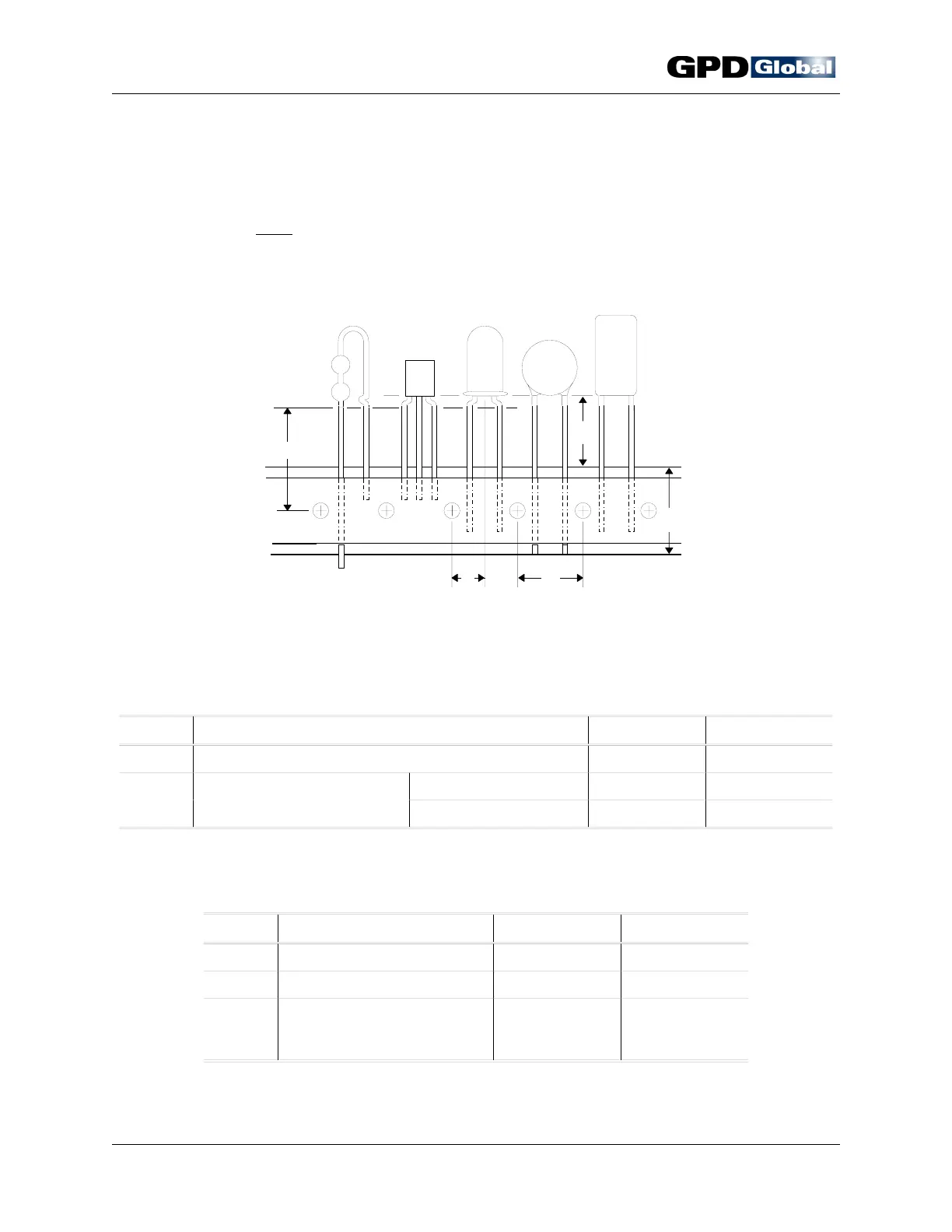
X
Y
C
B
A
CF-9 User's Guide
30 GPD Global 09/30/92
Figure 22 GPD's CF-9 Taping Specifications
Taping Specifications
The CF-9 will process components if taped to the E.I.A. standards listed below for taping of
radial components AND
there is a minimum of .300" (7.62 mm) operating clearance. In some
cases, standard tooling may work with less than this minimum operating clearance.
Custom tooling or custom taping may be required in certain instances.
GPD CF-9
Taping Specification Limits
Symbol Definition Inch MM
X Height to seating plane (formed leads) .300 ± .010 7.62 ± 0.25
Y Operating Clearance - All dies except style 8A .300 minimum 7.62 minimum
Seating plane (straight leads)
8A style die .350 minimum 8.89 minimum
E.I.A.
Taping Specification Limits
Symbol Definition Inch MM
A Component centering .250 ± .012 6.35 ± 0.30
B Sprocket hole pitch .500 ± .012 12.70 ± 0.30
C Carrier tape width .710 + .039 18.00 + 1.00
to to
—.020 —0.50