3
2
1
CF-9 User's Guide
18 GPD Global 09/30/92
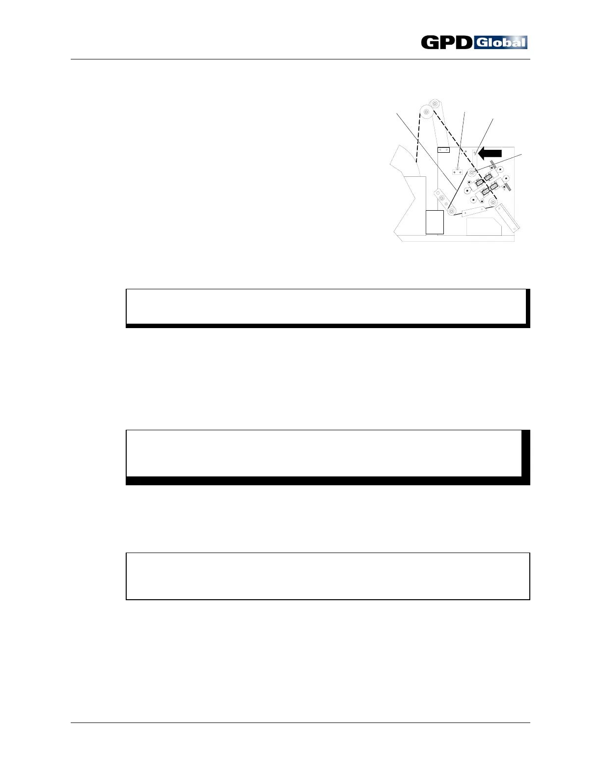
Figure 16
Align & Load
Components
Load Components
1. Press down on component tape pressure plate lever
(Figure 16, Item 3) to lift plate and open component
tape pathway.
2. Place tape's first hole over a pin on the transfer belt
(Item 1).
3. Release component tape pressure plate lever.
4. Using hand crank, manually index first component to
center of die Station 1.
5. Test all adjustments with the manual hand crank to
verify that component body will not be damaged by
forming dies or knives and that the component is
centered between the die station tooling.
C A U T I O N
If machine is not properly adjusted, damage to components and dies may result.
6. If further adjustments are necessary, repeat Setup procedure on page 13.
Power On
1. Close and lock safety shield in place with safety shield lock (Figure 16, Item 2).
W A R N I N G
For operator's safety, do not operate machine without safety shield in place and
do not defeat the safety switch.
2. Set speed control to zero (0). If using optional accessories, such as the footswitch or
electronic component counter, set power switch to AUX position. The auxiliary mode
indicator will light if the CF-9 is plugged in.
3. Press reset button.
NOTE
As a safety feature, power is not automatically restored when safety shield is
closed. Normal operations resume when reset button is pushed.
4. Turn power switch to ON.