T
1
B
1
9
8
1
2
3
4
5
CF-9 User's Guide
09/30/92 GPD Global 25
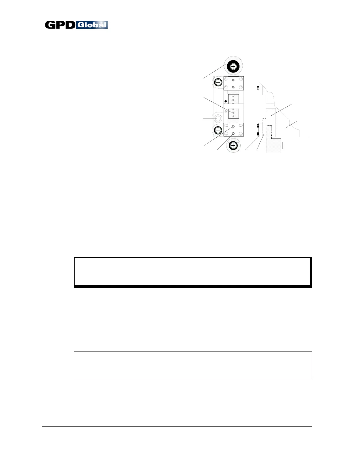
Figure 20 Die Block Assembly Slide Clearance
Slide Clearance
To adjust slide clearance:
1. Remove die block assembly. Station 1 die
block assembly is illustrated in Figure 20.
a. Remove from the CF-9:
• Tape exit chute
• Component transfer belt
• Transfer belt guide and
component tape pressure plate
(located on either side of
transfer belt)
b. Raise die block approximately 1"
(25.40 mm) from machine upright
plate using machine's die block
adjusting bolt (Figure 20, Item 3).
c. Remove mounting screws from micrometer scale's lower mounting block.
d. Turn die block adjusting bolt until die block no longer moves and then slide die block
straight off machine.
2. Clean parts.
a. Remove and discard set screws in cover plate (Figure 20, Item 6).
b. Remove slide (Item 9) from die block.
c. Use a degreaser (brake cleaner) to remove all oil from slide, die block, and wear
plate (Items 9, 8, and 7).
C A U T I O N
Do not expose micrometer scales to degreaser (brake cleaner) as it clouds the
clear face plate.
d. Measure all surfaces for wear and inspect for scratches and gouges. Replace parts
if raised material is visible on working plane.
e. Lightly stone all surfaces.
f. Blow dry all parts.
3. Reassemble die block.
a. Install slides in die block.
NOTE
Position slide with the eccentric bushing in the eccentric crank (Item 1) in die
block's top half (T1 or T2).
b. Slip wear plate face up between cover plate and slide.
c. Align wear plate counter sunk holes with cover plate set screws.
d. Install new set screws and lightly tighten.
e. With slides in closed position, locate a dial indicator on die mounting surfaces (Item