1
T
2
B 1
2
Forming
Style Series
Tape
1
T
T
2
T
2
1
T
2
5
B 1 2 B 2 5
B
1
B
2
1
2
3
2
1
CF-9 User's Guide
09/30/92 GPD Global 9
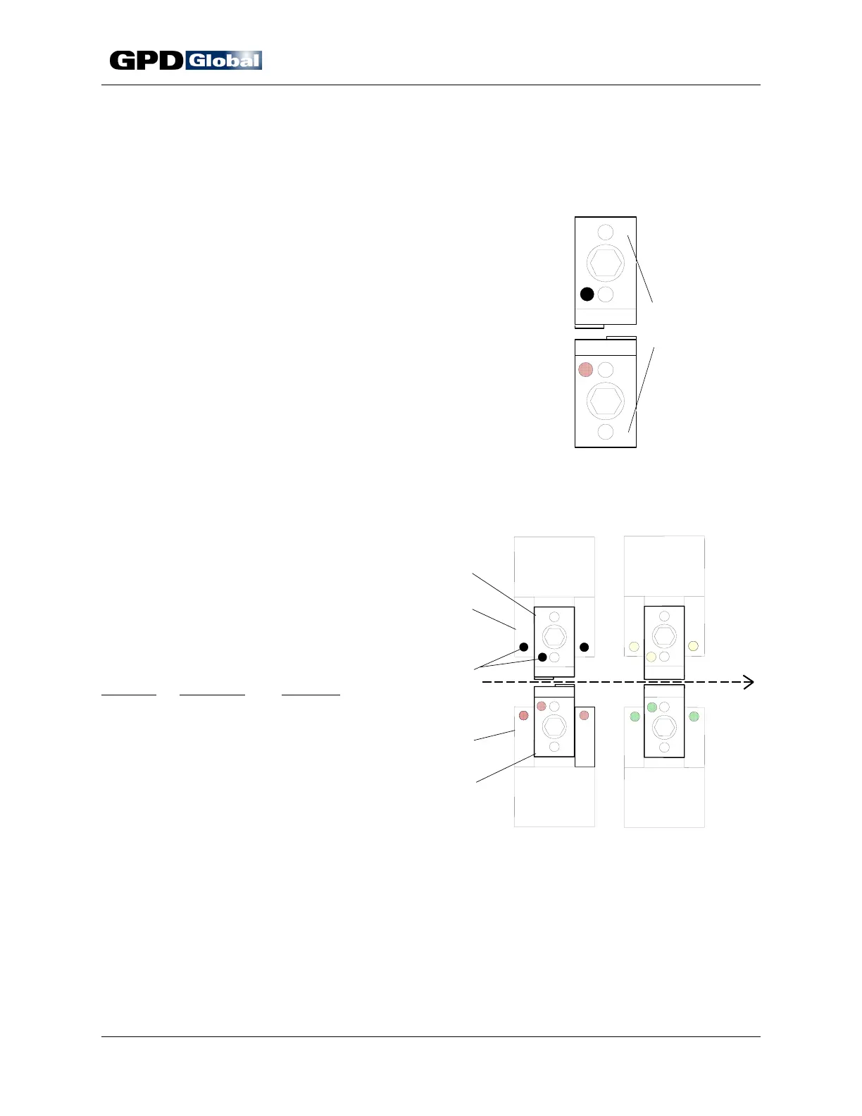
Figure 5
Die Forming Style Series
Figure 6 Die & Station Markings
Die Markings
Dies and knives are paired and stamp marked with the following
symbols so each can be readily identified and installed in the
correct station position:
• Forming Style Series Number
• Installation Marking
• Installation Color Dot
Forming Style Series
The forming style series is stamped on its right hand side of
each die and knife (Figure 5). Refer to the Die Information
appendix for specifics.
Installation Marking
Installation Color Dot
Characters are stamped on the left hand side of
each die half (Figure 6, Item 1) to indicate proper
die position in the forming and cutting stations.
Corresponding markings are stamped on each
station's stationary plate (Item 2). A color dot
(Item 3) associated with installation location is
also stamped on each die half and stationary
plate.
Marking
Color Dot Location
T1 Black Top die, Station 1
B1 Red Bottom die, Station 1
T2 Yellow Top die, Station 2
B2 Green Bottom die, Station 2