1
2
3
CF-9 User's Guide
09/30/92 GPD Global 17
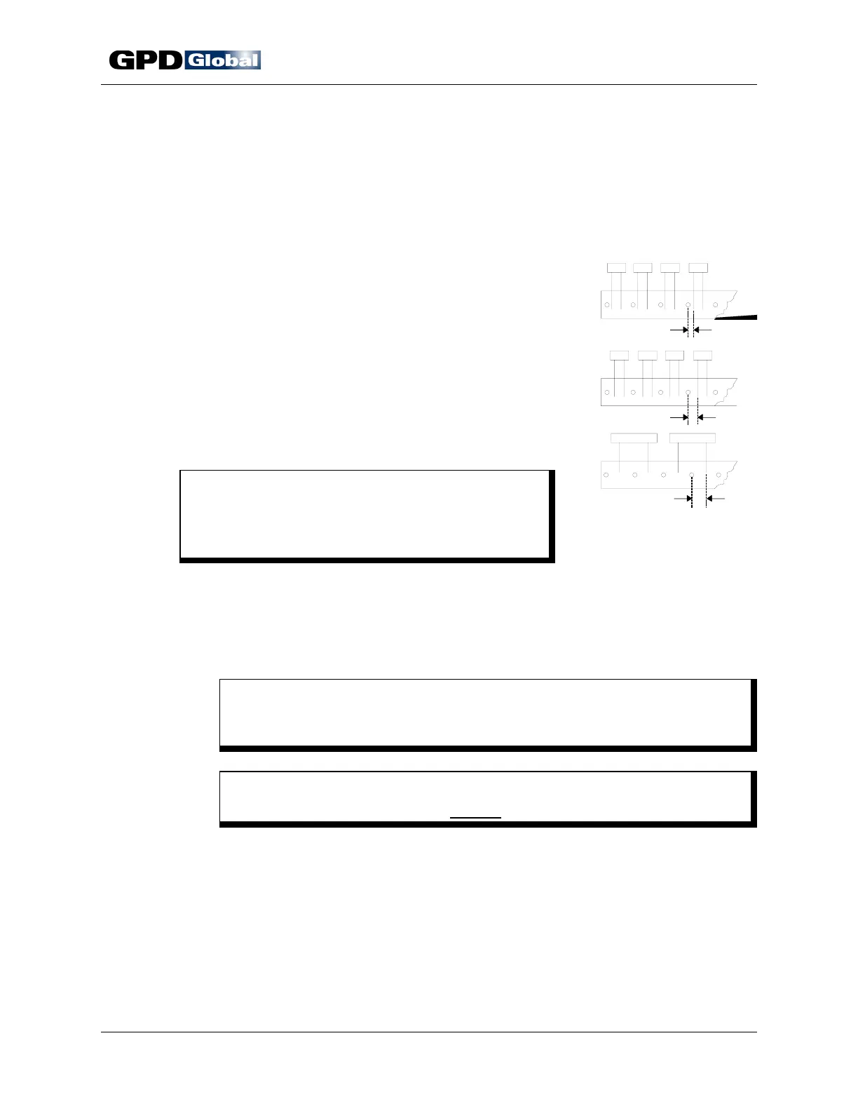
Figure 15 Component
Position Relative to Tape Hole
4. Record your micrometer setting. Then machine can be setup quickly the next
time you process the same component type.
5. Repeat Station Adjustment procedure for remaining die station.
Component Alignment
The CF-9 indexes exactly 1/2" (12.70 mm) every time,
however, component position relative to the tape hole
may vary from your last run due to variances between
vendors or lots because:
• Distance from tape hole to component lead wire
may vary (Figure 15, Item 1).
• Tape hole may be located between or under
component (Items 2 & 3).
A variance requires readjusting component alignment
with die stations — a simple matter of repositioning a
pulley (Figure 16, Item 4).
C A U T I O N
Testing component position relative to dies
MUST be done prior to automatic machine
operations.
To align components with die stations:
1. Manually index machine with hand crank just until components are centered
between dies and just before die touches component wires. Turn hand crank
slowly while visually inspecting for the relative position between components
and tape holes.
C A U T I O N
Dies should just start coming together - they should NOT be closed or
touching component.
C A U T I O N
DO NOT rotate mechanisms in reverse to check timing.
2. Loosen bolt in drive pulley (Figure 16, Item 4) with supplied 3/16" wrench.
3. Manually turn pulley in either direction to centrally position a component
between each die station.
4. Lock pulley in its new position by re-tightening the bolt.
5. Repeat step 1 to recheck tape alignment.