2
B
2
123 4
Large Ejector
Bracket
Component
Body Center
Line
1/32"
1/32"
Small Ejector
Bracket
CF-9 User's Guide
09/30/92 GPD Global 15
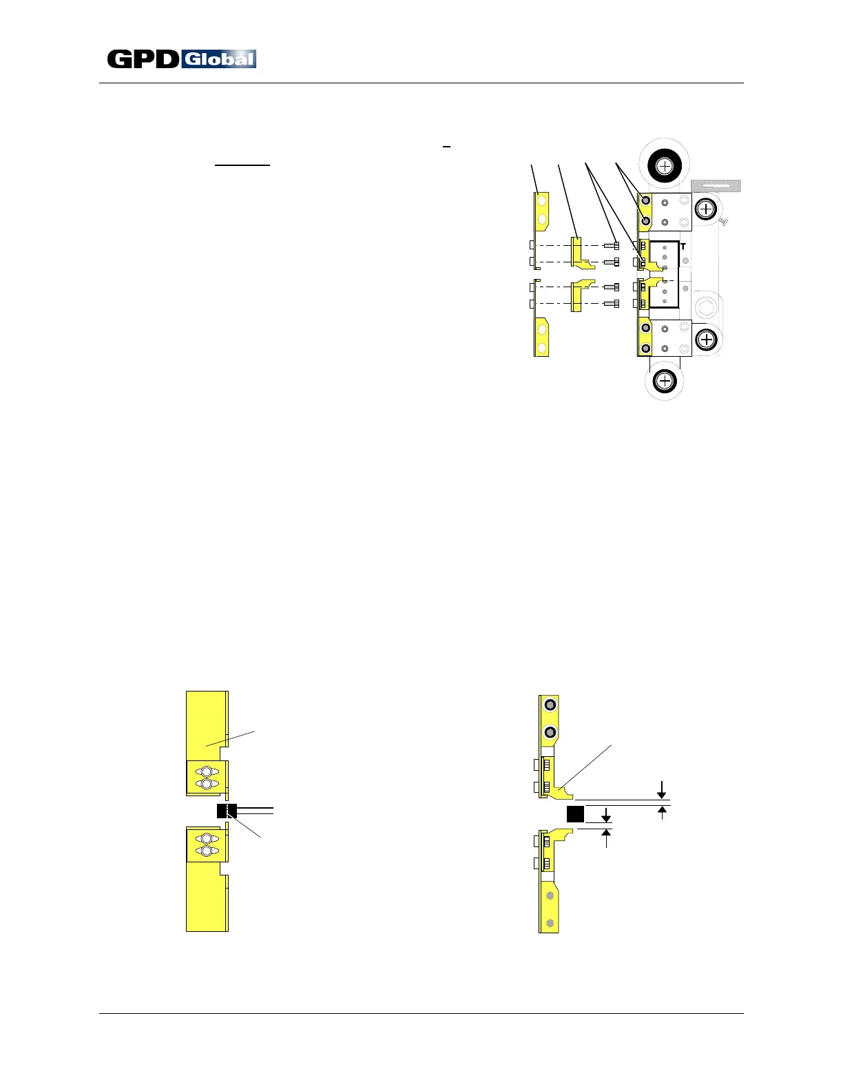
Figure 10 Ejector Brackets
Figure 11 Adjust Large Ejector Bracket
Figure 12 Adjust Small Ejector Bracket
6. Install and adjust ejector brackets if
required. Required usage is indicated for
each die, when appropriate, in the CF-9
Component Forming Die Catalog. Certain
complicated lead forms require ejector
bracket installation to insure that
component does not remain in die. If
ejector bracket installation and adjustment
is not required, skip to Station Adjustment
on page 16.
Suggestion: Remove the small ejector
brackets when not required to simplify die
installation.
Two sets of ejector brackets are factory
mounted on die Station 2 (Figure 10).
Each large ejector bracket (Item 1)
mounts to the Station 2 die block assembly with two screws (Item 4). Each
small ejector bracket (Item 2) mounts to the large ejector bracket with two
screws (Item 3).
Adjust for Component Body Thickness: Adjust for Component Body Height:
a. Loosen screws (Figure 10, Item 4). a. Loosen screws (Figure 10, Item 3).
b. Adjust each large ejector bracket b. Align center line of component body
(Item 1) to obtain an air gap of between small ejector brackets as
approximately 1/32" (0.794 mm) as illustrated in Figure 12.
illustrated in Figure 11. c. Tighten screws.
c. Tighten screws.