1
T
T
12
B
B
1
2
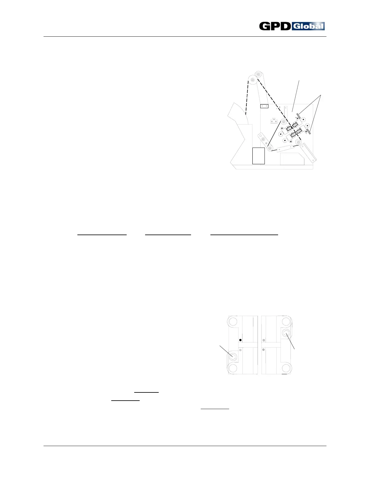
Station 1
Adjusting Bolt
Station 2
Adjusting Bolt
CF-9 User's Guide
16 GPD Global 09/30/92
Figure 13 Station Position Adjustment
Figure 14
Die Block Assembly Adjusting Bolts
Station Adjustment
The CF-9's die stations are independently
adjustable to control forming and cutting
locations. The action performed on component
leads by each die station can be relocated from
a zero (0) position. GPD suggests setting the
zero (0) reference point at the machine's upright
plate (Figure 13, Item 1). This position also
corresponds with the lead wire point of
attachment to the tape. Refer to Taping
Specifications on page 30.
Backlash is eliminated during station adjustment
by three (3) beveled washers located on each
station adjusting bolt.
The standard micrometer scale (Item 2) attached to each station, indicates the
distance from the component's point of attachment on the tape to the point of station
action on the component lead. These scales are accurate to .0005" (0.0127 mm).
Cut Lead Length
Station Position Station Action Location
Longest Fully retracted Zero (0) position - the point at which
Shortest Fully extended The point as near as possible to the
component attaches to tape.
component body. Each extension
movement of station position creates a
correspondingly shorter lead length.
To adjust station position:
1. Position die block against
machine upright plate.
2. Turn on micrometer scale and
reset to zero (0).
3. Adjust die station using
supplied 1/4" T-handle wrench
in station die block adjusting
bolt (Figure 14).
a. To extend station, turn
wrench counter-
clockwise.
b. To retract station, turn wrench clockwise
.