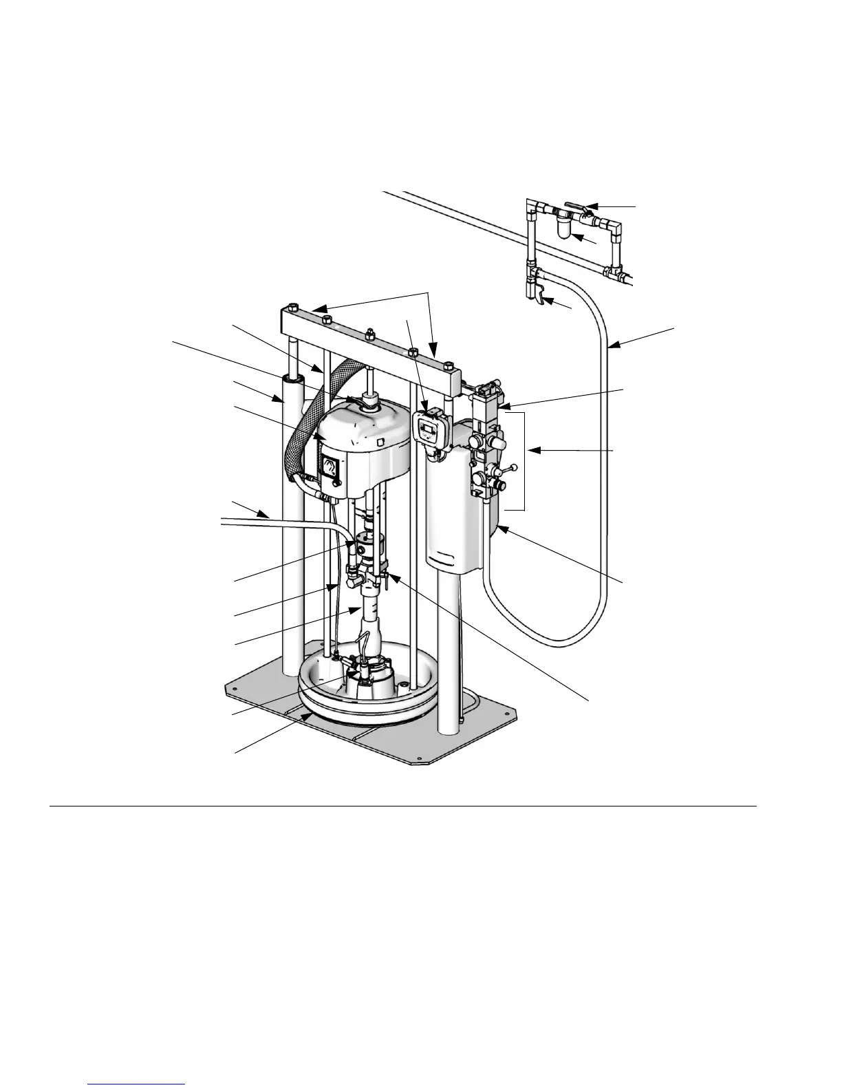
Component Identification
10 313527ZAD
Component Identification
D200 3 in. and D200s 6.5 in. Dual Post
Key:
A Ram Assembly
B Air Motor
C Displacement Pump
D Platen
F Remote DataTrak (single ram systems) or
Display Module (tandem systems)
G Integrated Air Controls (see F
IG.3)
H Air Motor Lift Ring
J Platen Bleed Port
K Power Supply Box (under shrouding)
M Blowoff Air Supply Line
N Platen Lift Rod
P Pump Bleed Valve
R Enclosed Wet Cup
S Fluid Line (not supplied)
T Air Line (not supplied)
U Air Line Drain Valve (not supplied)
V Air Filter (not supplied)
W Bleed Type Air Shutoff Valve (not supplied)
X Air Motor Solenoid
FIG.1
T
D
W
V
J
G
K
E
U
M
N
S
CM14BA Model
Shown
A
B
R
C
P
X
TI10430a
H
(Note: Do not use motor
lift ring to lift entire
system.)
Lift Locations