Repair
36 313527ZAD
Power Supply
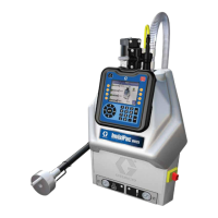
Remove 24 VDC Module
1. Turn external 24 VDC power source off.
2. Remove shrouding covers. See DataTrak Kit parts
illustration on page 62.
3. Remove two screws (156), two washers (164), and
press cover plate (160) up from the bottom. Then
slide to front of ram to remove.
4. Disconnect power supply output cable from CAN
cable (163).
5. Remove quick disconnects from rocker switch termi-
nals 1 and 4.
6. Remove protective earthing conductor from the PE
terminal marked .
7. Remove screws (159) and 24 VDC power supply
module (154) from power supply mounting bracket
(151. See parts illustration on page 54.
8. Remove screws (155) and power switch (157) from
power supply mounting bracket (151).
9. Clean and inspect all parts for wear or damage.
Replace as needed.
Replace 24 VDC Fuses
1. Complete steps 1 and 2 from Remove 24 VDC
Module.
2. Open the fuse holder and remove two fuses. Install
new fuses (165).
Install 24 VDC Module
1. Ensure that the external 24 VDC power source is
off.
2. Mount 24 VDC module (154) on mounting bracket
(151).
3. Mount power switch (159) on mounting bracket
(151).
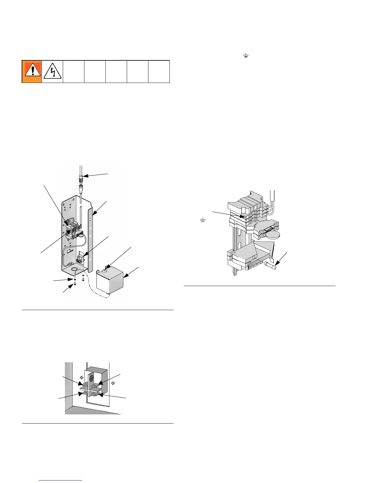
4. Attach quick disconnects on cable from 24 VDC
module (154) to ter minals on power switch (157).
a. The black wire connects to terminal 4, adjacent
to terminal marked (-).
b. The red wire connects to terminal 1, adjacent to
terminal marked (+).
5. Install power supply output cable to CAN cable
(163).
FIG.36
FIG.37
TI10853A
160
156
151
154
PE
163
161
164
159
1
TI10985A
2 (+)
4
5 (-)
FIG.38
TI11170A
165
PE
Terminal