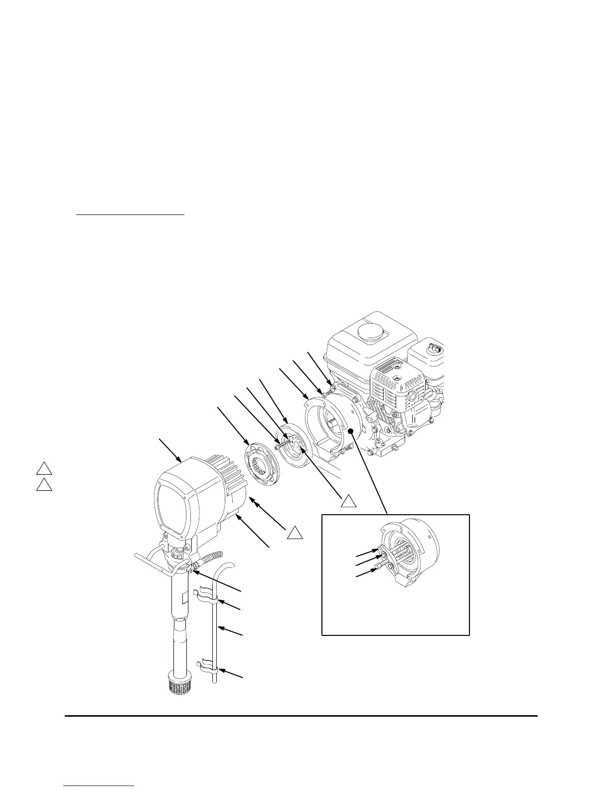
Clutch
NOTE: The clutch assembly (4) includes the armature
(4a) and rotor (4b). The armature and rotor must be re-
placed
together so they wear evenly
.
NOTE: If the pinion assembly (19) is not yet separated
from the clutch housing (2), follow Steps 1 to 4. Other-
wise,
start at Step 5.
NOTE:
Refer to Fig. 1
1 for this procedure.
1. Follow
the
Pressure Relief Procedure W
arning
on
page
14.
2. Disconnect the hose (59) from the displacement
pump. For the upright cart only
, remove the spring
clips (1
12, 1
14) and drain hose (1
13).
3. Remove the bottom two screws and lockwashers
(10, 11) from the front of the clutch housing (2) and
then
the remaining three of them.
4. Tap lightly on the back of the bearing housing (21)
with
a plastic
mallet to loosen the assembly (D) from
the
clutch housing. Pull the assembly away
.
5. The armature (4a) was removed with the pinion
housing.
Remove the armature from the pinion
hub.
6. There
are two ways to remove the rotor (4b).
a. Remove the four socket head capscrews (16)
and lockwashers (11). Install two of the screws
in the threaded holes in the rotor. Alternately
tighten
the screws until the rotor comes off. See
Fig.
1
1.
b. You
can use a standard steering
wheel puller (A).
However
, two 1/4–22– x 3
or
4 in. long screws (B)
are also needed.
Replace
the short screws of the
steering
wheel puller with the longer screws (B).
Turn the screws (B) into the threaded holes of
the rotor (4b). Tighten the capscrew (C) of the
tool
until the rotor comes of
f. See Fig. 1
1.
7. Skip
ahead to
Reassembly
,
page 27, Step 6, or con
-
tinue
on the next page.
Fig. 11
A
B
C
Using
a steering wheel
puller to remove rotor
10
16
11
4b
11
4a
19
59
D
112
113
114
2
1
2
Threaded holes
Pinion
shaft located
in back
2
1