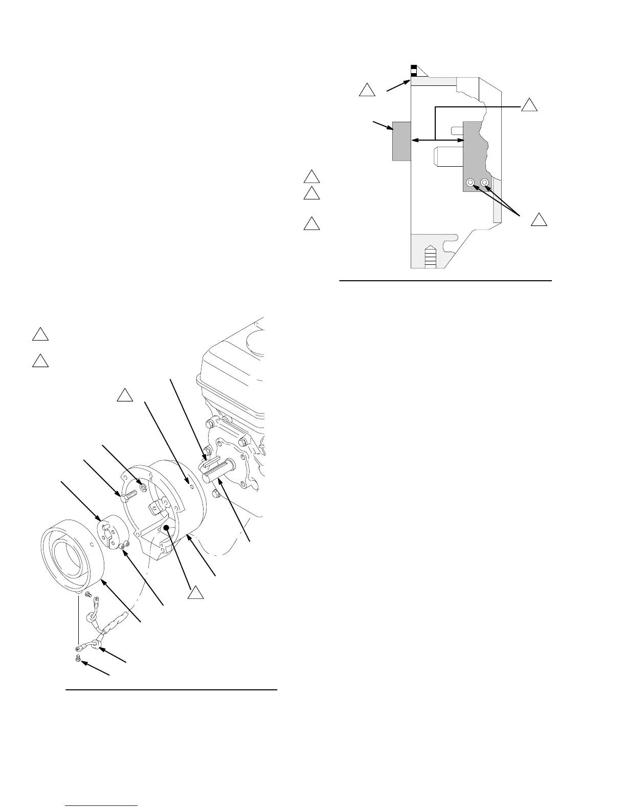
Reassembly
1. Install the clutch housing (2), capscrews (8) and
lockwashers
(9) on the engine. See Fig. 17.
2.
Install the engine shaft
key (13).
See Fig. 17.
3. Press
the
clamp (3)
onto the engine shaft. Maintain
the
1.99 in.
+/– 0.01 (50.55 mm) dimension shown in
Fig.
18.
To check the dimension, place a rigid, straight steel
bar
(B) across the face of the clutch housing (2). Use
an accurate measuring device to measure the dis-
tance
between the bar and the face of the clamp. Ad
-
just
the clamp as necessary
. T
orque the two screws
(16)
to 120 in–lb (14 N.m).
4. Install
the
field
(6)
in the clutch housing (2). W
orking
through the slot in the clutch housing, connect the
wires of the harness (96) to the screws (98) in both
places on the field. Pull the plastic caps (C) up and
snap
them over the screws. With
the setscrew holes
in
the field and the clutch housing (2) aligned, tighten
the
setscrews (12) oppositely
and evenly
, to 27 in–lb
(3.2
N.m). See Fig. 17.
Fig. 17
12
6
3
8
9
2
13
98
96
16
A
004
1
2
Torque
oppositely
and evenly to
27 in–lb (3.2 N.m)
1
Slot
2
Fig.
18
16
2
B
1.99”
(50.55 mm)
0050
1
3
2
Face of housing
T
orque to
120 in–lb
(14 N.m)
1
2
3