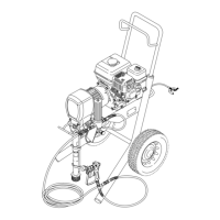
Reassembly
5. Place
the
engine (1)
assembly on the cart. Align the
mounting
holes. Carefully guide the engine wire
(D)
and wiring harness (96) from the field, through the
appropriate
grommets (66)
in the mounting plate (E).
Install the flange screws (14) and locknuts (111).
Torque to 15 ft–lb (20.4 N.m). Install the capscrew
(15), lockwasher (80) and washer (99) from under
the
engine mounting plate to the clutch housing
(2).
Connect
the engine wire (D) to the red wire, and con
-
nect
the black and
white wires as shown in the Detail
drawing
in Fig. 19.
6. Be
sure the face of the
rotor (4b)
and the
field is free
of all oil and contaminants. Remove any burrs on the
outside
edge of the rotor
. Install the rotor
, lockwash
-
ers (11) and capscrews (16). T
orque the capscrews
to 7 ft–lb (9.5 N.m). See Fig. 19.
After installing the rotor (4b), check the clearance-
between
the outside diameter of the rotor and the in
-
side
diameter of the field. The clearance must be at
least 0.010 in. (0.25 mm) all the way around. Use
shim
stock or feeler gauge. If necessary
, loosen
the
setscrews (12) and reposition the field. Tighten the
setscrews
evenly to 27 in–lb (3.2 N.m).
Be sure the face of the armature (4a) is clean. As-
semble
the armature to the shaft in
the pinion hous
-
ing
(19). A retaining ring located within the armature
makes
it dif
ficult to assemble these parts. Follow this
procedure for the best results. First, engage a few
splines
of both
parts. While they are engaged, use a
screwdriver
to gently push the retaining ring into the
armature,
and finish engaging the splines. Push the
armature onto the shaft until it contacts the ring
(19m).
See Fig. 19.
7. Assemble the pinion housing (19) to the clutch
housing,
using the capscrews (10) and
lockwashers
(11).
See Fig. 19.
Fig. 19
E
66
Ref 14,1
11
RED
BLACK
WHITE
97
66
RED
BLACK
WHITE
111
99
80
15
4a
11
4b
6
2
11
10
1
16
96
D
0157
014601460147
19
View
from under engine mounting plate on Lo–Boy cart
V
iew from under engine mounting plate on upright cart
12
14
1
3
4
2
T
orque to 7 ft–lb 99.5 N.m)
1
Face must be clean
Spline
T
o field (ref. 96)
T
o engine (ref. D)
5
6
2
T
orque to 15 ft–lb (20.4 N.m)
3
4
5
5
6
6

 Loading...