14
15
16
1
2
3
45
6
7
8
9
10
11
13
1
2
3
4
5
6
7
14
17
11
13
17
19
18
15
8
10
0158
0159
12
16
19
L
L
L
L
L
15a
15d
15c
15b
3Z7–847
Rev B
Supplement
to manual 307–847
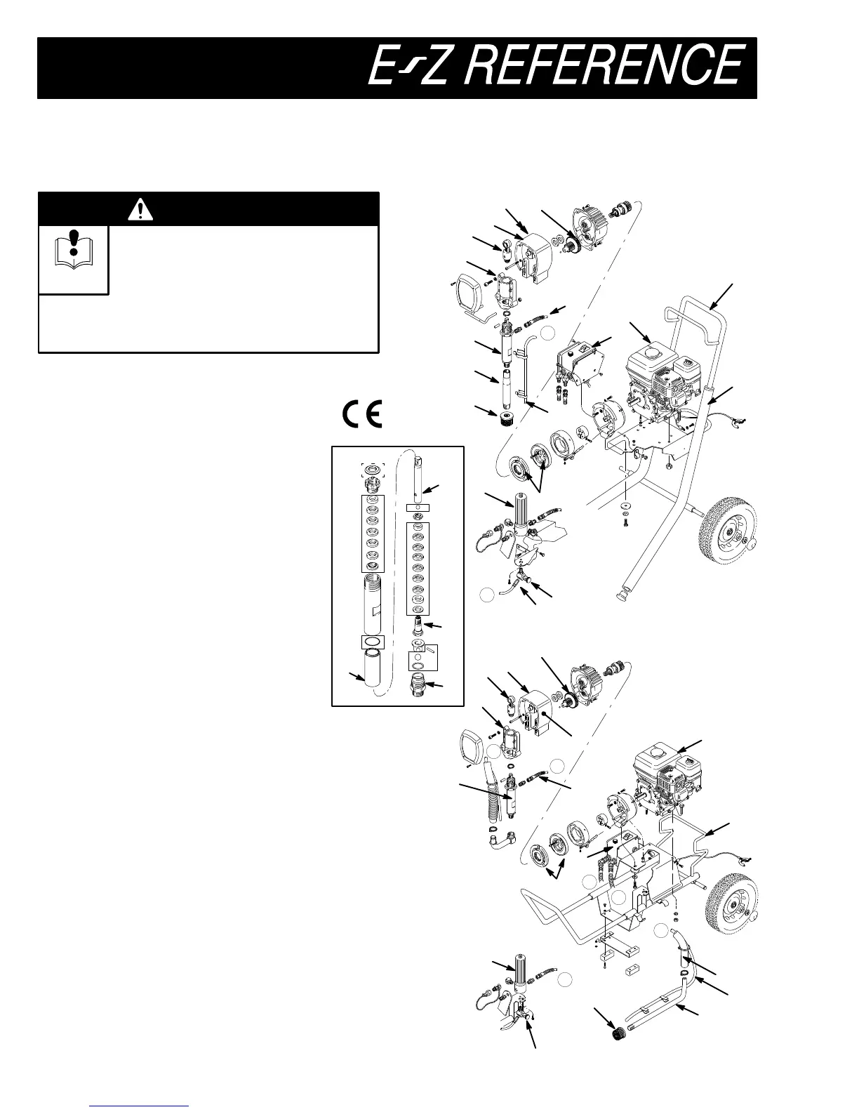
GM5000 Airless Paint Sprayer
INJECTION
HAZARD
This is only a quick reference to the
features and frequently ordered parts of
this sprayer
. T
o reduce the risk of
serious injury
, including fluid injection, while op
-
erating or repairing this sprayer
, follow the warn
-
ings and instructions in manual 307–847.
WARNING
INSTRUCTIONS
Model 220–886, Series C
Basic sprayer with upright cart
Model 231–052
Complete sprayer with upright cart
Model 222–488, Series A
Basic sprayer with LoBoy cart
Model 231–085
Complete sprayer with LoBoy cart
Ref Upright LoBoy
No.
Part No. Part No.
Description
1
220–639 Same
Bearing Housing
2
220–640 Same
Connecting Rod
3
220–879 Same
Drive Housing
4
Y185–953 Same
Danger Label
5
220–919 Same
Gear Reducer
6
220–849 222–516 Hose
7
222–369 Same
Pressure Control
8
108–802 Same Engine
9
220–918 None
Handle & Hose Rack
10
236–788 222–612 Cart Frame
1
1
224–775 222–198
Pressure Drain V
alve
12
108–982 None T
ube Connector
13
214–570 Same
Fluid FIlter
14
236–568 Same
Clutch Assembly
15
220–872 Same
Displacement Pump
15a 183–361 Same
.Cylinder Sleeve
15b 220–630 Same
.Piston Rod
15c 220–631 Same
.Piston V
alve
15d 220–629 Same
.Intake V
alve
16
183–423 170–957
Intake/Suction T
ube
17
181–072 Same Strainer
18
None 185–381
Suction Hose
19
186–495 805–077
Bypass T
ube
Y
Extra danger labels are available for free.
Packing Repair Kit
220–877
Includes parts marked with a
L
Sleeve Removal T
ool 224–788
Required for removing pump sleeve