syncFURNACE OD Instruction & Installation Manual – Rev 09 Pg. 42 of 81
FAN-COIL INSTALLATION:
General Requirements:
1. syncFURNACE OD fan-coil installation must conform to local building codes.
2. syncFURNACE OD can only be installed in up-flow installation types.
3. It is highly recommended to install so that the bottom front panel is easily accessible after
installation for future maintenance and service of the blower. Keep in mind routing of electrical,
gas and plumbing lines.
4. Use industry approved standards to size and install the supply and return air duct system.
5. DO NOT operate the fan-coil with an external static pressure that exceeds rating for specific model
number – Higher external static pressures may cause erratic operation – Product Warranty will be
null and void if the product is installed in applications with static pressure greater than value listed
in specification table inside this manual & on product rating plate.
6. DO NOT bring in return air from the back of the unit. Return air can only be brought in from the
sides or the bottom.
7. For bottom return air connections, cut open the bottom side panel using industry acceptable
practises. NOTE: Pay special attention to not damage blower and blower wiring.
8. Ensure a tight seal between the return & supply duct connections. Use aluminum foil tape to
ensure air tight seal.
9. When sizing duct-work, a maximum flow velocity of 800 fpm is desired.
Filter Assembly & Filters:
1. syncFURNACE OD is NOT provided with a filter rack or filter. Both of these items are field supplied.
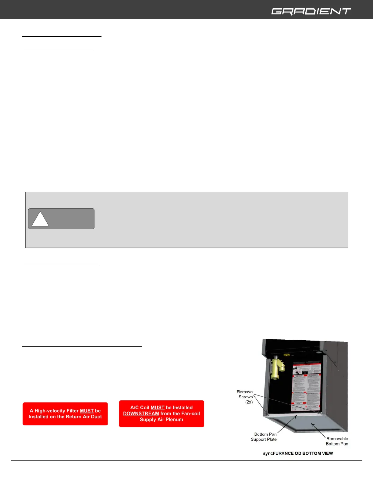
2. A field supplied hi-velocity filter MUST be installed on the return air duct.
a. Recommended sizes –
Side or Bottom Return 17.5” Wide Models –16” x 25” x 1” (406mmx635mmx25.4mm)
Side or Bottom Return All Other Models –20” x 25” x 1” (508mmx635mmx25.4mm)
[Note: For better air flow & filtration we recommend 4” thick filter]
3. For side return air installation - Filter must be installed so that a MIN 1” (25.4mm)
(Recommended 2” [51mm]) of space is between the side of the product and the filter face.
Removing Panel for Bottom Return Air:
1. Remove screws (2x) on front side of plate.
2. Twist plate down and out.
3. Pull out removable pan.
4. Re-install plate and attach screws (2x).
High voltage is at all times present at the fan-coil blower motor. Disconnect power to
syncFURNACE OD before removing or replacing or servicing motor. Wait at least 5
minutes after disconnecting power before opening motor. Failure to follow this
WARNING could result in minor personal injury or product and property damage.
Return Air must not be drawn from a room where any fossil fuel burning appliance (eg.
Water heater, furnace) is installed.