syncFURNACE OD Instruction & Installation Manual – Rev 09 Pg. 5 of 81
Clean Combustion Chamber [At Minimum, Perform Annually]: ........................................................ 60
Check and Clean Condensation Line and Trap [At Minimum, Perform Semi-Annually]:........................ 60
Flue Gas Vent & Air Intake Sealing [At Minimum, Perform Annually]: ............................................... 61
Igniter & Flame Sensor Electrodes [At Minimum, Perform Annually]: ............................................... 61
Burner Flame [At Minimum, Perform Annually]: ............................................................................ 61
Additional Service and Maintenance Inspections: ........................................................................... 61
11. Troubleshooting > .............................................................................................................. 62
Appendix A: Internal Wiring Diagram > ................................................................................... 65
Appendix B: Sequence of Events > ........................................................................................... 66
Appendix C: Replacement Parts List >...................................................................................... 67
Appendix D: Handling Instructions for Refractory Cement Fibers (RFC) > ............................... 69
Appendix E: Annual Inspection & Maintenance Record > ......................................................... 70
Appendix F: Internal Pump Specifications > ........................................................................... 72
Appendix G: Heat Exchanger Specification > ........................................................................... 73
Appendix H: Fan-Coil PERFORMANCE > .................................................................................... 74
5L MODEL: ............................................................................................................................... 74
10L MODEL: ............................................................................................................................. 75
14L MODEL: ............................................................................................................................. 76
18L MODEL: ............................................................................................................................. 77
22L MODEL: ............................................................................................................................. 78
Appendix I: Temporary Construction Heat > ............................................................................ 79
Appendix I: Example Humidifier Wiring Diagram > .................................................................. 80
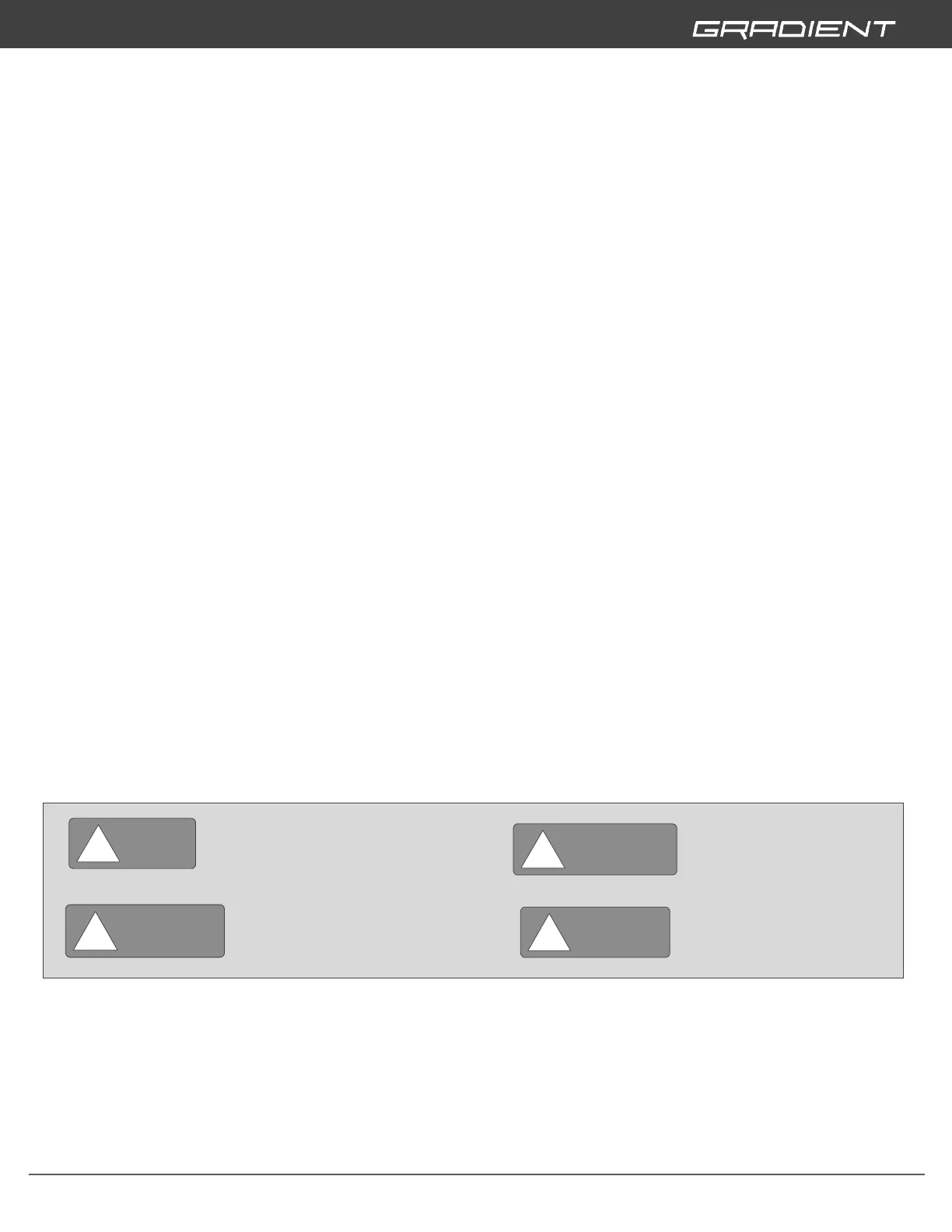
1. GUIDELINE TO SYMBOLS >